RETIRED - Pi Wedge Hookup Guide
This Tutorial is Retired!
This tutorial covers concepts or technologies that are no longer current. It's still here for you to read and enjoy, but may not be as useful as our newest tutorials.
View the updated tutorial: RETIRED - Pi Wedge B+ Hookup Guide
 Byron J.
Pin Mapping
Revisions
The pins on the Raspberry Pi changed between Revision 1 and Revision 2 - a few signals were reassigned. The physical connection is the same, but you'll need to know which version of Pi you're using to address the pins correctly.
The Wedge is labeled with the Revision 2 labels. You'll need to translate a few things if you're using a Revision 1 Pi. In short - to use the Wedge with a Revision 1 Raspberry Pi, do the following.
- Be sure to use
/dev/I2C0instead of/dev/I2C1. - Use GPIO 21 instead of GPIO 27.
Alternately, use a software library such as Wiring Pi that can identify the revision and abstract the pin numbers. We'll cover WiringPi in more detail in the software section.
Signal Location
The Pi Wedge reorganizes the I/O pins on the Pi, putting similar functions on adjacent pins. The SPI, I2C and UART signals are all grouped near each other.
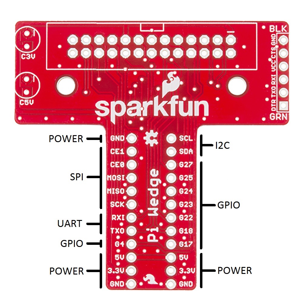
The pins are labeled, though the labels are short to fit the space available on the PCB. The UART, SPI and I2C pins are marked with their communication bus functions, but they can also available as GPIO pins when initialized in that mode.
The following table denotes the assignment of signals on the Pi Wedge, including the peripheral and alternate GPIO assignments where appropriate.
| Function | GPIO# | Function | GPIO# | |
| Ground | R0: SCL0 R1: SCL1 | R0: GPIO1 R1: GPIO3 | ||
| SPI0 Chip Enable 1 | GPIO 7 | R0: SDA0 R1: SDA1 | R0: GPIO0 R1: GPIO2 | |
| SPI0 Chip Enable 0 | GPIO 8 | R1: GPIO 21 R2: GPIO 27 | ||
| SPI0 MOSI | GPIO 10 | GPIO 25 | ||
| SPI0 MISO | GPIO 9 | GPIO 24 | ||
| SPI0 Shift Clock | GPIO 11 | GPIO 23 | ||
| UART Rx | GPIO 15 | GPIO 22 | ||
| UART Tx | GPIO 14 | GPIO 18 | ||
| GPIO 4 | GPIO 17 | |||
| 5V | 5V | |||
| 3.3V | 3.3V | |||
| Ground | Ground |