RETIRED - Pi Wedge Hookup Guide
This Tutorial is Retired!
This tutorial covers concepts or technologies that are no longer current. It's still here for you to read and enjoy, but may not be as useful as our newest tutorials.
View the updated tutorial: RETIRED - Pi Wedge B+ Hookup Guide
 Byron J.
Assembly
The Pi Wedge comes to you as loose parts, which you need to assemble before you can use it. The following steps will guide you through the assembly process.
Kit Contents
Let's start by reviewing the contents of the Pi wedge kit.
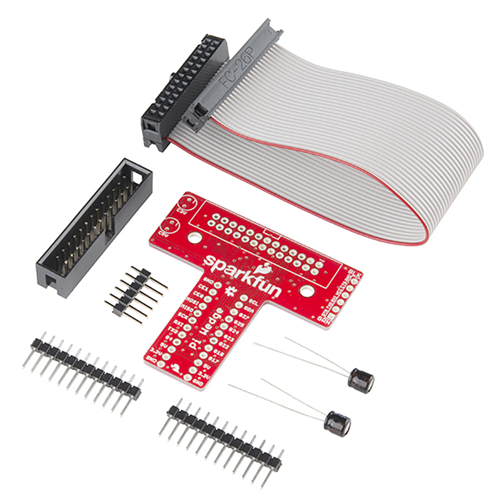
You should have the following parts.
- Ribbon cable
- Pi Wedge PCB
- 26-pin shrouded header
- 6-pin straight header
- 2x 12-pin straight headers
- 2x 10 uF 25V electrolytic capacitors
Instructions
Assembly of the Pi Wedge should be mostly obvious and straightforward. One thing to notice is that components are soldered to both sides of the board. The headers that interface with the breadboard are on the bottom of the board, soldered from the top. The other components go on the top, and are soldered from the bottom.
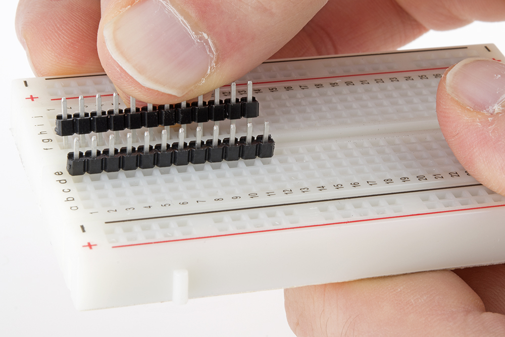
Pin Alignment
To keep the breadboard pins properly spaced and aligned while you solder, you can use your breadboard as an assembly jig. Simply insert the 12-pin headers in the breadboard...
...then place the PCB over them, and solder it in place. Notice that the PCB is placed over the pins so that the signal labels are facing up.
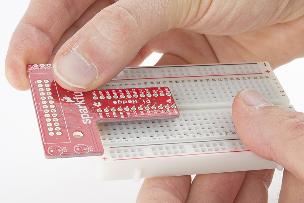
Be careful not to overheat and melt the breadboard while soldering the pins on. Zig-zagging between the rows will help distribute the heat. Also, somewhat counter-intuitively, using a hotter setting on your soldering iron will allow you to work more quickly, minimizing the risk of melting the breadboard.
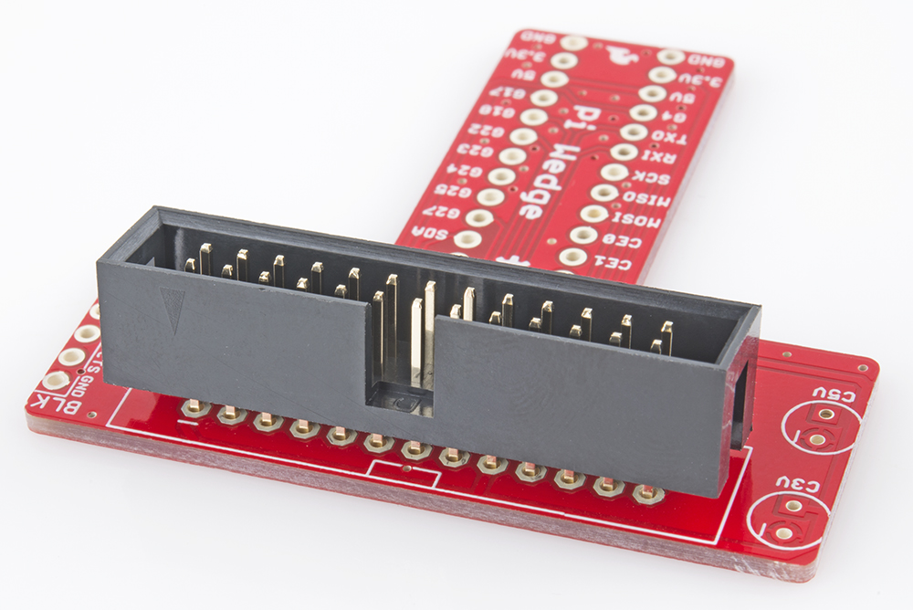
Shrouded Header
The shrouded header has a notch that keeps the ribbon cable properly oriented. The notch should be lined up with the corresponding rectangle in the PCB silkscreen.
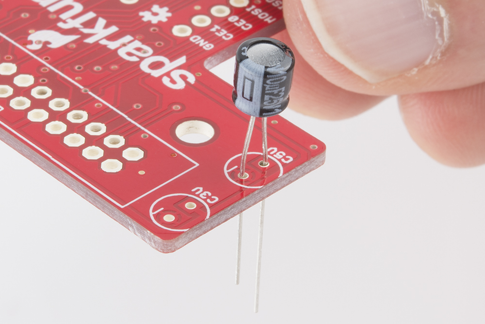
Capacitors
The electrolytic capacitors are polarized. The body has a band of "-" signs near the negative lead, which should be inserted into the PCB hole marked with the - sign. The negative lead is also shorter than the positive lead.
Serial Adapter Connector
The 6-pin header is soldered onto the PCB across from the capacitors.
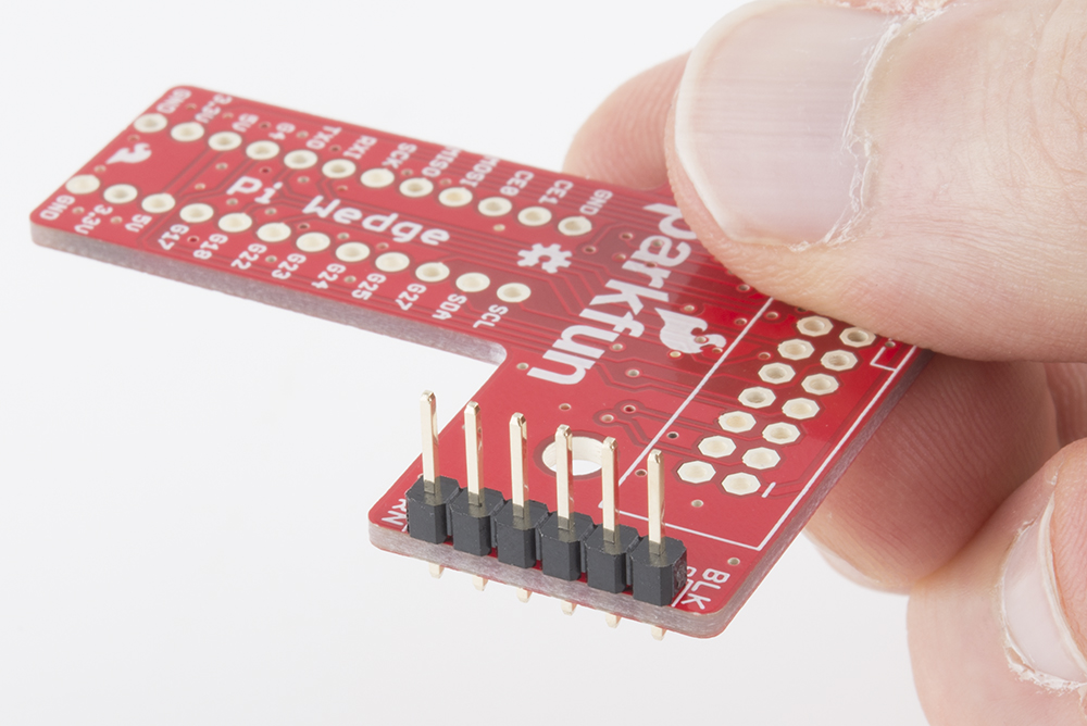
If you want a lower profile assembly, you can substitute a right-angle header for the straight pins in the kit.
Connection
With the wedge soldered together, you're ready to attach it to your Pi, and test it out.
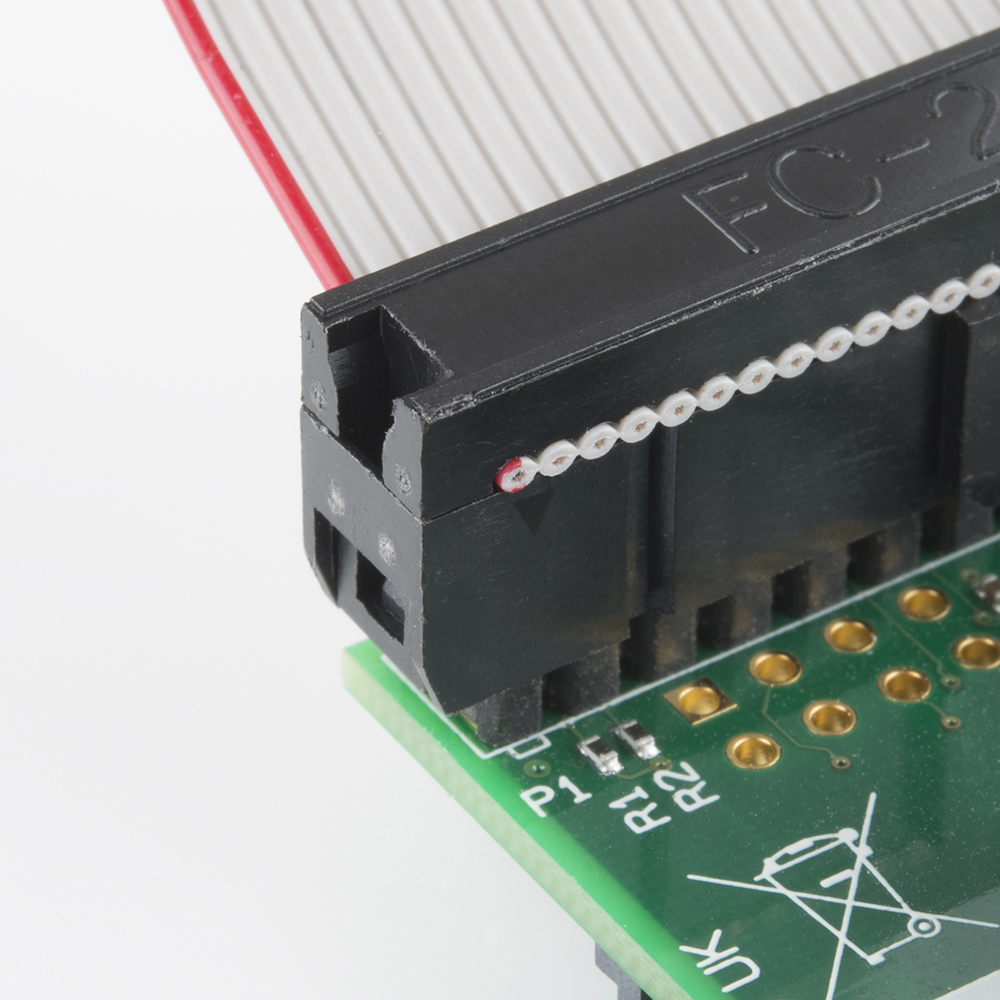
The ribbon cable is polarized. On the Pi Wedge, the tooth on the cable will interface with the notch in the shrouded header.
The header on the Pi itself doesn't have anything to help guarantee the alignment. You'll need to take care that it gets connected properly. Pin 1 on the Pi is marked with a small rectangle in the silkscreen layer. The ribbon cable connector is embossed with (a barely visible) small triangle that marks pin 1, and the first pin is also coded on the wire, such as the red stripe in the photo below (though it may also be another color, such as black or dark blue).
The FTDI connector also needs to be aligned correctly. Be sure to match up the "grn" and "blk" markings on both boards.
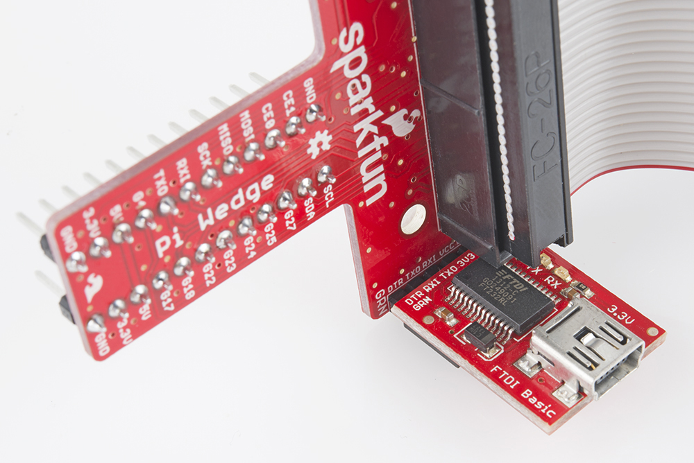
On the next page, we'll explore how the signals from the Pi are mapped to the Wedge.