RETIRED - MG2639 Cellular Shield Hookup Guide
This Tutorial is Retired!
This tutorial covers concepts or technologies that are no longer current. It's still here for you to read and enjoy, but may not be as useful as our newest tutorials.
 jimblom
Supplying Power
Beyond finding a suitable SIM card, the most important part of getting the MG2639 Shield working is supplying it with enough power.
Power Supply Requirements
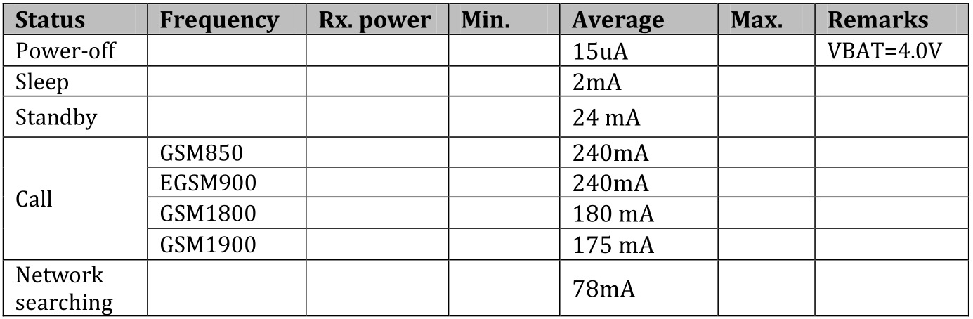
Depending on which state it's in, the MG2639 module can be a relatively power-hungry device. The maximum current draw of the shield is around 350mA. It usually won't pull that much, but may require around 260mA during phone calls or 80mA during network transmissions. This chart from the datasheet summarizes what you may expect:
In selecting your power supply, it's important to note that the MG2639 Shield will not work if your Arduino is only powered off USB -- an external power supply is required to power both the Arduino and Shield. The shield includes a 3.8V regulator to supply the MG2639 within its 3.4-4.2V range. That regulator is sourced by the Arduino's VIN pin. We recommend a barrel jack power supply with a voltage output in the acceptable range of your Arduino (or at least 4.5V for the shield).
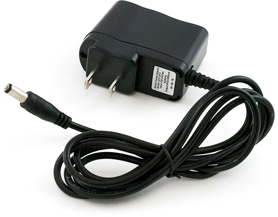
Our 9V power supply is a good choice, and the one we used in our prototyping and testing.
(Optional) Using a Battery Supply
The operating voltage range of the MG2639 (3.4-4.2V) makes it an ideal candidate for direct LiPo battery supply. The Shield can be powered through a LiPo battery, but there are some adjustments you'll need to make to the bottom-side jumpers before doing so.
As a starting point, here is the schematic of the shield's voltage regulator and power input circuitry:
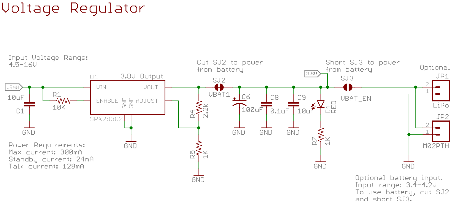
In order to power off a battery instead of the Arduino's VIN pin ("VRAW" on the schematic), you need to cut SJ2 and short SJ3.
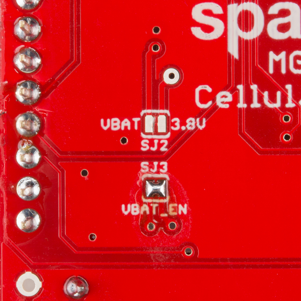
SJ2 will prevent the 3.8V regulator from supplying a competing voltage to the battery. SJ3 will allow the battery to directly supply the MG2639.
To connect the battery to the shield, two connectors are broken out on the top side of the board, labeled "BATT". One connector is a footprint for our 2-Pin JST Connectors, which mates with our catalog of single-cell LiPo's. The other is a simple 0.1" 2-pin header.
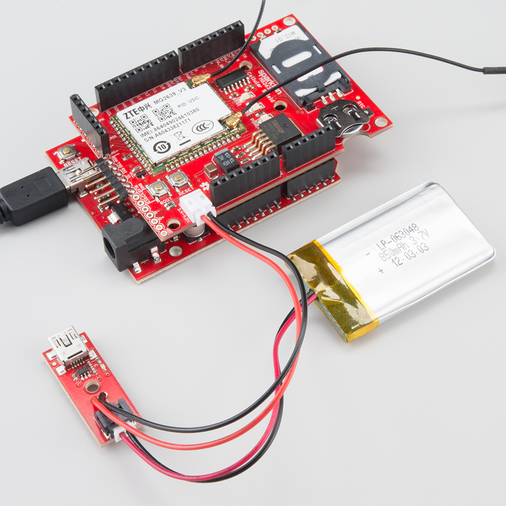
The battery supply will not be fed back into the Arduino, so you'll need to either find a separate power supply for the microcontroller board, or split the battery in two directions.