RETIRED - MG2639 Cellular Shield Hookup Guide
This Tutorial is Retired!
This tutorial covers concepts or technologies that are no longer current. It's still here for you to read and enjoy, but may not be as useful as our newest tutorials.
 jimblom
Hardware Overview
Before you get to connecting the MG2639 Cellular Shield to your Arduino, you should familiarize yourself with the features and abilities of the board. This page serves as an overview of the shield's components and pin-outs. It also looks at some of the "hidden" features of the board.
Component Overview
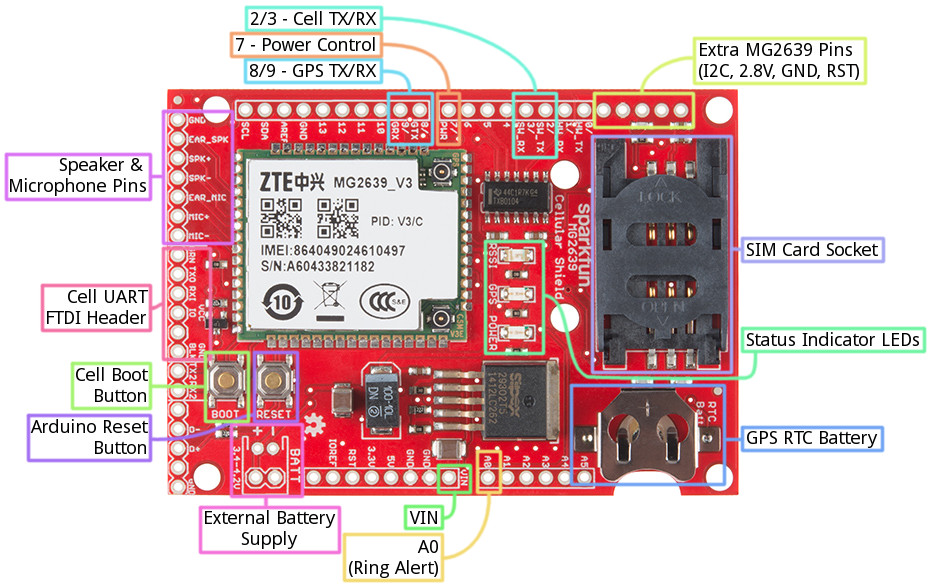
For a quick overview, here are most of the components of interest on the shield:
Arduino Pins Used
One of the most important characteristics of a shield are the Arduino pins used, here's a list of the pins used by the cellular shield:
| Arduino Pin | MG2639 Function | Notes |
|---|---|---|
| VIN | Power Supply | The MG2639 requires that the Arduino be supplied with an external power source (USB won't cut it). This pin is disconnectable via a jumper. |
| A0 | RING Alert | This pin will go low when a phone call is coming in. |
| 2 | Cell UART TX | Cell module's data output (4800 baud). |
| 3 | Cell UART RX | Cell module's data receive (4800 baud). |
| 7 | Cell boot pin | This pin has the same control over the module as the BOOT button (explained below). |
| 8 | GPS UART TX | GPS module's data output (115200 baud). |
| 9 | GPS UART RX | GPS module's data receive. |
Cell and GPS UARTs
Communication with the cellular and GPS module's occurs on two separate serial UARTs. To leave the Arduino's hardware UART free for debugging and uploading sketches, both UARTs are broken out to digital pins -- intended for use with the SoftwareSerial library.
Because the SoftwareSerial library can't reliably support high-ish baud rates, we've intentionally slowed down the MG2639's cellular UART to 4800 bps, rather than the module's default bit rate of 115200. This slower rate ensure data reliability, and gives the Arduino some extra time to process large strings.
The GPS UART is hard-coded to 115200 baud, which make it harder to use with SoftwareSerial. Instead, we recommend using the AltSoftSerial library with this part of the module.
Either of the two UARTS (the cell or GPS) can be switched over to the Arduino's hardware UART. Check out the "Jumpers" section below for more information.
LED Status Indicators
There are a trio of LEDs on the MG2639 Cellular Shield which indicate connectivity or power status:
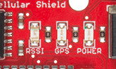
- POWER -- This red LED is connected to the MG2639 module's power supply line. If this LED is on, the module is receiving power.
- RSSI -- This green LED indicates the status of your cellular network. It'll blink at various rates to show what state it's in:
- OFF -- The module is powering on (assuming it has power).
- 1 Hz blink -- Module is idle.
- 3 Hz blink -- Searching for a network.
- 5 Hz blink -- Module is in a traffic state (a phone call or data transmission).
- GPS -- GPS fix indicator. This yellow LED will illuminate when the MG2639's GPS module gets a solid fix.
Boot & Reset Buttons
Two buttons labeled "BOOT" and "RESET" are built into the shield. The "RESET" button is simply the Arduino reset, it'll have no direct effect on the MG2639.
The "BOOT" button connects to the MG2639's PWRKEY input, which turns the module on or off. This button works exactly as you might expect any cell phone power button to work. If the module is off, hold the button down for 2-5 seconds then release to turn it on. If the module is on and you hold the button down and release, it'll turn off.
Control of this button is shared between the physical button itself and Arduino pin 7. The Arduino pulling pin 7 LOW has the same effect as pushing the button down. This gives the Arduino machine control over the module's ON/OFF status.
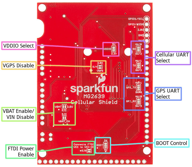
Bottom-Side Jumpers
To keep the Shield as multi-purpose as possible, there are a number of jumpers on the backside that can be used to switch the interface pins or power supply.
To open any of these jumpers, use a hobby knife, and remove the small trace between any two connected pads. To connect a jumper, solder a small solder joint between two pads.
Here's a quick rundown of each jumper:
- VDDIO -- This jumper selects the voltage for logic running into the high side of the shield's TXB0104 level shifter. It defaults to 5V but can be switched to 3.3V if your application requires.
- Cellular UART RX and TX -- These jumpers allow you to switch the cellular module's RX and TX between either pins 2 and 3 or 0 and 1. That means selecting between a software (2/3) or hardware (0/1) UART.
- GPS_TX and GPS_RX -- Like the other UART jumpers, these allow you to set the GPS module's UART to either software (8/9) or hardware (1/0).
- VGPS Disable (SJ4) -- This jumper controls power delivery to the shield's GPS module. If you don't want to use the MG2639's GPS module, and want to avoid the power loss it incurs, cut this jumper.
- VBAT Enable/Disable (SJ2 and SJ3) -- If you want to power the Cellular Shield from a single-cell lithium polymer battery, you'll need to attack both of these jumpers. Shorting SJ3 will connect the JST-footprint connector directly to the module's power supply. Opening SJ2 will disconnect the voltage regulator output from the rest of the circuit.
- FTDI Power Enable (SJ8) -- If you want to use an FTDI Basic to troubleshoot the MG2639's UART, this jumper will allow you to power the VDDIO line with the FTDI's VCC pin.
- BOOT Control -- This jumper allows you to remove Arduino pin 7 (mislabeled "6" near the jumper) from the MG2639's boot button.
Note: If you decide to use the hardware UART, make sure to only connect one of the two modules to the 0/1 pins! If both are connected, bus contention and data loss will occur.