Real Time Clock Module Hookup Guide
 jimblom
 Introduction
The SparkFun Real Time Clock Module is a simple breakout board for the DS1307 real-time clock (RTC). It can accurately keep track of seconds, minutes, hours, days, months, and years for almost a decade, so your microcontroller doesn't have to. It's the perfect component for clocks, calendars, or any other time-keeping project.
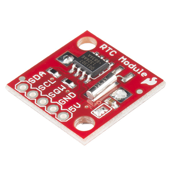
The IC on the SparkFun RTC Module is the Maxim DS1307. It features a two-wire I2C interface and even includes a square wave output pin. Plus, with a battery backup, the DS1307 can keep time for almost a decade or more (typically 17 years)!
This tutorial serves as a general introduction to the DS1307 and the SparkFun Real Time Clock Module. It covers both the hardware and firmware requirements of the breakout -- documenting both example wiring and Arduino code for the chip.
Suggested Materials
You'll need a handful of extra parts to get the RTC Module up-and-running. Below are the components used in this tutorial, if you want to follow along.
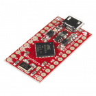
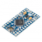
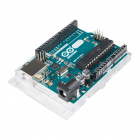
A microcontroller that supports I2C is required to communicate with the DS1307 and relay the RTC's data to the user. The SparkFun RedBoard or Arduino Uno are popular options for this role, but just about any microcontroller development board should work. (The firmware examples use an Arduino library, if that serves as any extra motivation to use an Arduino.)

Four or five jumper wires and a breadboard help interface the RTC Module to your Arduino. To insert the breakout into the breadboard, you'll need to solder headers to the pins. (Don't forget a soldering iron and solder!)


The RTC Module does include a 12mm Coin Cell Battery. You shouldn't need one for a long while, but if you want to stock up on the lithium batteries, the option is there.
Suggested Reading
The SparkFun RTC Module is a very beginner-friendly breakout board. There are, however, still a few concepts you should be familiar with. If any of the tutorial titles below sound foreign to you, consider giving them a look-through: