Real Time Clock Module Hookup Guide
 jimblom
Hardware Hookup
Before you can insert the RTC Module into a breadboard, or otherwise connect it to your microcontroller, you'll need to solder something to the 5-pin header. If you plan on breadboarding with the chip, we recommend straight male headers. Female headers or even a few strips of wire are other good options.
Headers can be assembled on either side of the board -- one will give you easy view of the pin labels, the other easy access to the coin cell. If you choose the label-view, you may need to add a little air gap between the header shroud and the board, so the header/breadboard can clear the height of the coin cell.
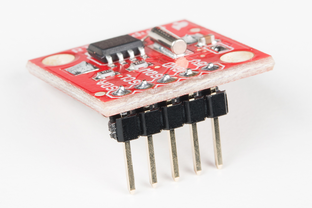
Breadboards can make a great "third hand" while you're soldering these headers -- especially in this case, where you need to take the height of the battery holder into consideration.
Example Circuit
The DS1307's I2C interface means, to interface with the chip, all you need is four wires between your microcontroller and the breakout board: power, ground, data, and clock. The SQW pin can optionally be wired to the Arduino and used as a pulse-counter.
Here is an example hookup diagram demonstrating how to connect the board up to an SparkFun RedBoard:
