Real Time Clock Module Hookup Guide
 jimblom
Hardware Overview
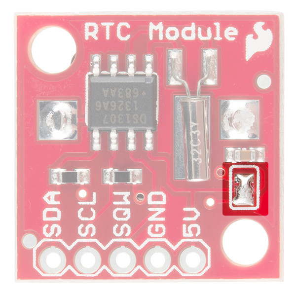
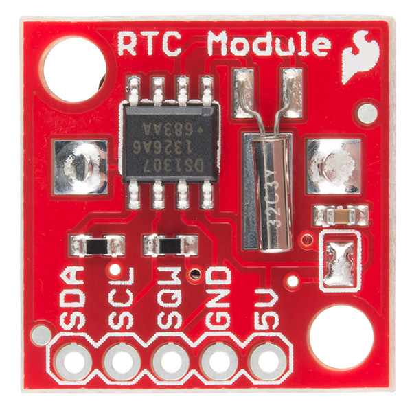
The RTC Module surrounds the DS1307 with all of the components it needs to count time, communicate, and maintain power. The communication and power pins are all broken out to a single, 5-pin header, with pin labels on the top side of the board.
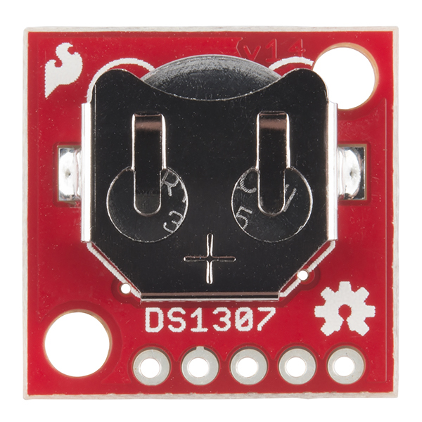
The bottom side of the breakout consists almost entirely of the 12mm coin cell battery holder.
Pinout
The five pin breakouts on the board provide access to the communication interface and allow you to supply the chip's primary power source.
| Pin Label | Input/Output | Description |
|---|---|---|
| SDA | Bi-directional | I2C bus data line |
| SCL | Input | I2C bus clock line |
| SQW | Output | Configurable square-wave output |
| GND | Supply Input | Ground (0V) supply |
| 5V | Supply Input | DS1307 VCC power supply input |
Powering the DS1307
The RTC module breakout board does not include any voltage regulation, so power supplied to the "5V" pin should be kept within the DS1307's recommended operating range: 4.5 to 5.5V.
The chip is designed to be as low-power as possible. During communication bursts, the chip may consume upward of 1.5mA, but it will run at closer to 200µA.
When the primary power supply is removed and the chip is running off its backup battery, it will consume between 300-800nA (depending on whether the SQW pins is configured as an output).
Assuming it has capacity of 47mAh, a fully charged 12mm coin cell battery can keep the DS1307 running for up to 17.88 years if the chip consumes its minimum 300nA!
(47mAh / 300nA = 156666.67 hours = 6527.78 days = 17.87 years)
Using the SQW (Square Wave) Output Pin
Aside from its I2C pins, the DS1307 also features a configurable square wave output pin -- SQW. This pin can be configured to produce one of six signals, or it can be turned off.
| SQW State | Description |
|---|---|
| 1 Hz | Square wave at 1Hz |
| 4.096 kHz | Square wave at 4.096 kHz |
| 8.192 kHz | Square wave at 8.192 kHz |
| 32.768 kHz | Square wave at 32.768 kHz |
| 0 | Pin driven LOW (0V) |
| 1 | Pin driven high (5V) |
In order to use the SQW pin as an output driver, it must be connected to a pull-up resistor. A 10kΩ resistor, connected between SQW and 5V, should do the job.
I2C Pull-Up Resistor Disable
A small 3-way jumper, located on the top side of the board (below the brown-ish capacitor) is connects the on-board 4.7kΩ pull-up resistors to the 5V supply. If you need to deactivate these pull-ups, the jumper can be cleared — effectively removing the resistors from the circuit.
A little bit of solder wick and a touch of your soldering iron should remove the jumper's solder blob.