Qwiic Speaker Amp (TPA2016D2) Hookup Guide
 QCPete,
  bboyho
Hardware Overview
In this section, we will highlight the hardware and pins that are broken out on the Qwiic Speaker Amp (TPA2016D2). For more information on the amplifier, check out our Resources and Going Further.
Amplifier to Amplifier (Comparision of a few of SparkFun Audio Amps)
What distinguishes this audio amplifier from others is that it features volume control (i.e. gain), Dynamic Range Compression (DRC), Automatic Gain Control (AGC), enable/disable amplifier, and its ability to be configured through software via I2C. Its efficient class-D operation also means low heat and long battery life when driving 4Ω speakers at up to 2.8W in stereo, and 8Ω speakers at up to 1.7W in stereo. This is quite a bit more power than the mono amplifier (TPA2005D1) or Noisy Cricket stereo amplifier (LM4853). It won't shake a stadium but it will provide plenty of volume for your audio projects.
, release date September 2022") |
, SparkFun release date April 2018") |
, SparkFun release date March 2012") |
| Qwiic Speaker Amp (TPA2016D2) [ DEV-20690 ] |
Noisy Cricket Stereo Amp (LM4853) [ DEV-14475 ] |
Mono Amp (TPA2005D1) [ BOB-11044 ] |
The DRC and AGC is unique compared to other audio amplifiers. This is a powerful feature that allows you to "even out" the loud and quiet sections from your audio input. It also allows you to maximize the volume of your speakers. By fine-tuning the settings, you can get the most volume to prevent distortion of the audio signal. Using the DRC, AGC, and/or the limiter alone allows you to protect your speakers from getting damaged by extremely loud playback. We've written an extensive Arduino Library (shown later in this tutorial) that allows you to easily control all of the amplifier's features from simple gain control to advanced AGC. Note that you will need to send the configuration to the TPA2016D2 upon every power cycle.
Power
There are two ways to power the board:
- Screw Terminal
- Qwiic Cable
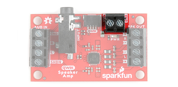
Power Screw Terminals
The Qwiic Speaker Amp requires an input voltage between 2.5V and 5.5V. You can insert wires through the two pin screw terminal labeled as VIN and GND. Using a higher voltage closer to the recommended input voltage will drive the speakers better and provide a louder sound.
Power Qwiic Cable
You can also provide power through the Qwiic Connector. This will provide 3.3V for the amplifier. Simply insert a Qwiic cable between your development board and the Qwiic Speaker Amp.
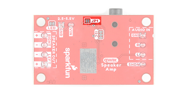
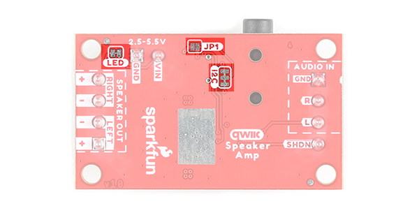
If you are powering the board through the Qwiic connector, make sure to add a solder jumper on JP1.
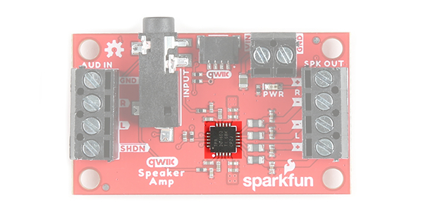
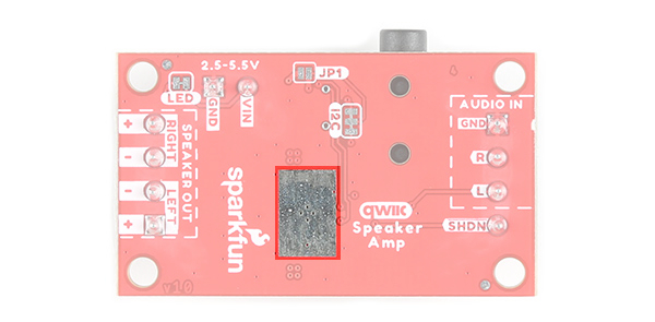
Thermal Dissipation
While the TPA2016D2 includes thermal protection, the exposed copper pour directly below the IC on the bottom of the board is added to the design for better thermal dissipation.
I2C and Qwiic
To communicate with the amplifier, you will need an I2C bus. The Qwiic system makes it easy to connect the TPA2016D2 to your projects via the Qwiic connector. You can add a Qwiic cable between the amplifier and development board to configure the TPA2016D2. The I2C address of the TPA2016D2 is 0x58 (unshifted). There are two 2.2kΩ pull-up resistors connected to the SDA and SCL lines.
Audio Input
There are two ways to provide an audio signal for the Qwiic Speaker Amp.
- 3.5mm TRS Connector
- Screw Terminals
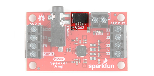
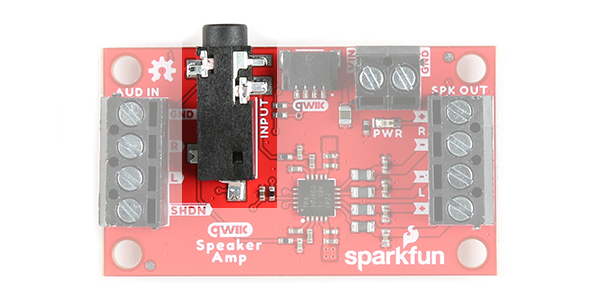
Audio Input 3.5mm TRS Connector
One method of providing an audio signal is through the 3.5mm TRS connector (labeled as INPUT). This is if you have a media player with a 3.5mm TRS connector as well. The tip is connected to the left audio input, the ring is connected to the right audio input, and the sleeve is connected to ground.
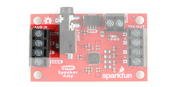
Audio Input Screw Terminals
The other method is to connect an audio signal to the audio in left (AUD IN, L) and right (AUD IN, R) pins that are broken out on the screw terminals. Just make sure to connect ground.
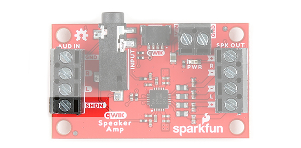
Shutdown
We broke out the shutdown pin (labeled as SHDN) by the audio input pins. This pin is active low. Connecting this pin with a wire to the ground pin will manually shutdown the Qwiic Speaker Amp.
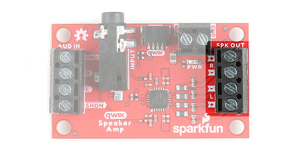
Speaker Output
The board includes differential stereo outputs for a left and right speaker. Below are some specifications from the datasheet that show what you may expect from each channel based on the speaker's impedance and voltage input.
- 1.7W per Channel into 8Ω at 5V
- 750mW per Channel into 8Ω at 3.6V
- 2.8W per Channel into 4Ω at 5V
- 1.5W per Channel into 4Ω at 3.6V
For an analog input on the left (AUD IN, L), make sure to place a speaker on the left "SPK OUT, +" and "SPK OUT,-" pins. For an analog input on the right (AUD IN, R), make sure to place a speaker on the right "SPK OUT, +" and "SPK OUT,-" pins.
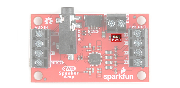
LED
There is one LED to indicate when power is applied to the Qwiic Speaker Amp. This is labeled as PWR. When power is applied to the board's VIN, the LED will light up. If jumper JP1 is closed, the LED will light up when the board is connected to a board through a Qwiic cable.
Jumpers
The following three jumpers are included.
- LED - By default, this jumper is closed and located on the bottom of the board. Cut this trace to disable the power LED that is connected to 3.3V.
- I2C - The I2C jumpers are closed by default. By cutting the traces between the jumper pads, it will disconnect to the 2.2kΩ pull-up resistors for the I2C bus. Most of the time you can leave these alone unless your project requires you to connect the pull-up resistors.
- JP1 - This jumper is open by default. For users that just want to provide power to the TPA2016D2 via the Qwiic cable's 3.3V line, add a solder jumper to the pads. Depending on the 3.3V voltage regulator that you are using, you may not have enough power to drive the speakers at their full potential as stated earlier.
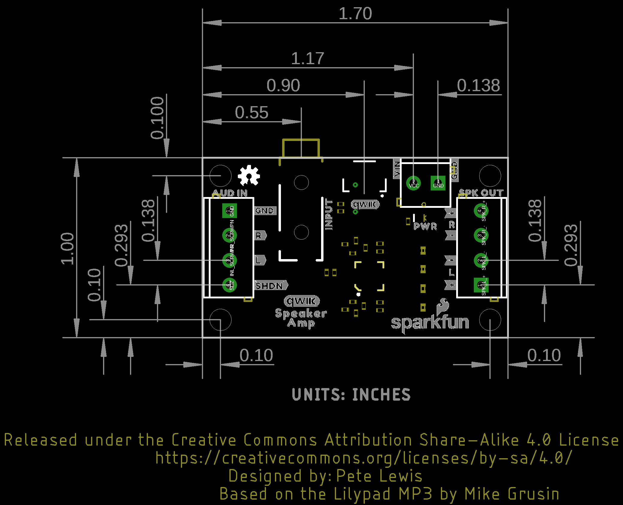
Board Dimensions
The overall length and width is about 1.70" x 1.00". This does not include the length of the 3.5mm TRS connector that is sticking slight out of the board. The board includes 4x mounting holes on the edge of the board.