Qwiic Speaker Amp (TPA2016D2) Hookup Guide
 QCPete,
  bboyho
Hardware Hookup
This board is great for projects that require you to amplify an audio signal for small, differential speakers. This breakout is also great when pairing it with your smartphone, computer, portable digital player, or any audio boards (such as the MP3 Trigger, Tsunami Super WAV Trigger, MP3 Player Shield, or Music Instrument Shield to name a few)! In this section, we will show you a few ways to connect to the Qwiic Speaker Amp.
Soldering Wire vs Quick Disconnects
Depending on your setup, you may need to strip some wire and solder the ends to terminals before connecting your speakers or power supply to the Qwiic Speaker Amp. You can also use jumper wires with male pins.
Working with Wire
How to Solder: Through-Hole Soldering
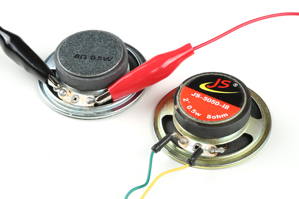
One example are the 8Ω small, cone speakers. These do not have wires connected to the tabs. The best method of connecting the cone speaker would be to solder wires to the tabs. In this case, jumper wires with male pins were soldered the ends. You could also connect to the tabs using alligator clips for a temporary connection. However, you need to ensure that the alligator clips are not touching the speaker frame as this will short the speaker pins and blow out the Qwiic Speaker Amp.
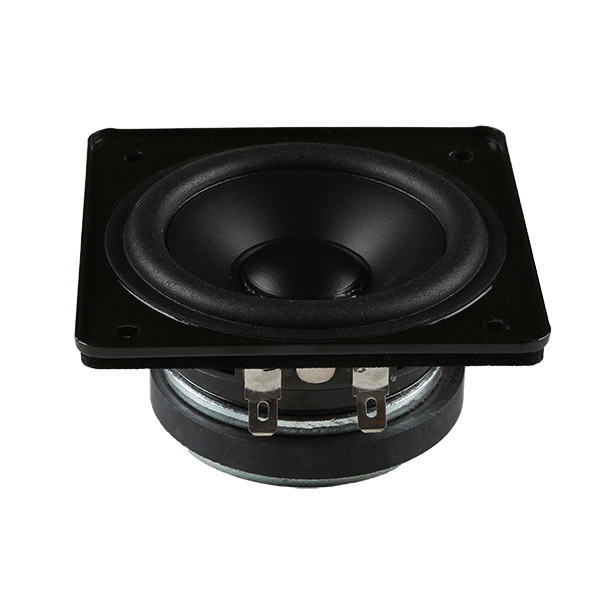
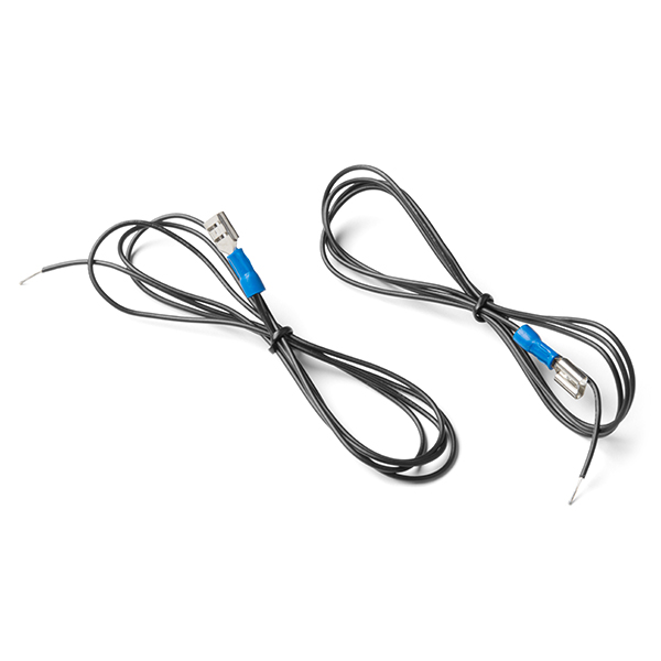
For larger speakers (like the Wide Frequency Range Speaker - 3in) have 1/4" tabs. You could use 1/4" spade quick disconnects with crimped wire for a secure connection or crimp them yourself.
 |
 |
| Wide Frequency Range Speaker - 3in [ COM-18379 ] |
Spade Connector Wire - Female [ COM-14166 ] |
Audio In via 3.5mm TRS Audio Jack
For a quick connection to audio boards and portable digital players with a 3.5mm TRS audio jack, you can connect a TRS cable between the two.

Audio In via Screw Terminals
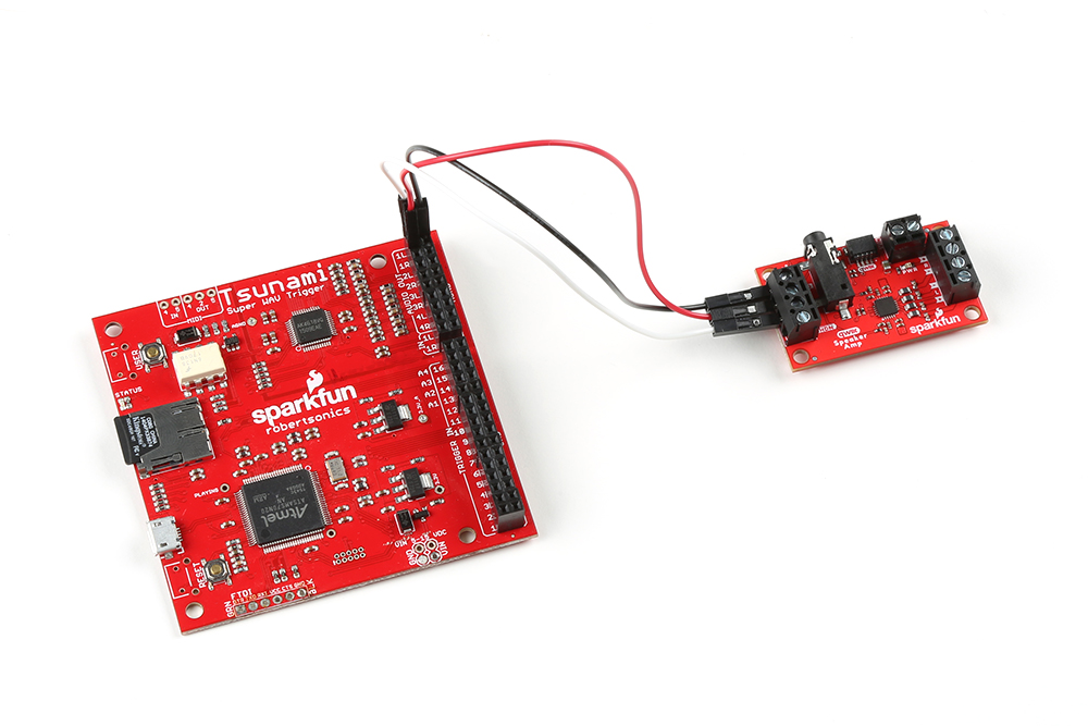
You can also insert a jumper wire to the R, L, and GND from your audio board. In this case, we used an old Tsunami Super WAV Trigger to connect to the Qwiic Speaker Amp. Depending the audio board that you use, additional soldering may be required. Just make sure to connect your stereo output between both boards (i.e. R to R, L to L, and GND to GND between the boards).
Power In via Screw Terminals
For the a louder output, you will want to go this route with a separate power supply as shown below. Insert power into the "VIN" and "GND" terminals between the power supply and the Qwiic Speaker Amp. Make sure that the voltage that you are applying to the "VIN" terminal is between 2.5V and 5V. In this case, we used a 5V wall adapter with barrel jack, female barrel jack adapter. We then connected some stripped wire from "+" to "VIN" and "-" to "GND".

Power In via Qwiic Cable
If you would like to power the board with your Arduino using Qwiic cable, you can simply insert a Qwiic cable between the two connectors. In this case we used a RedBoard Plus to power the Qwiic Spaker Amp.

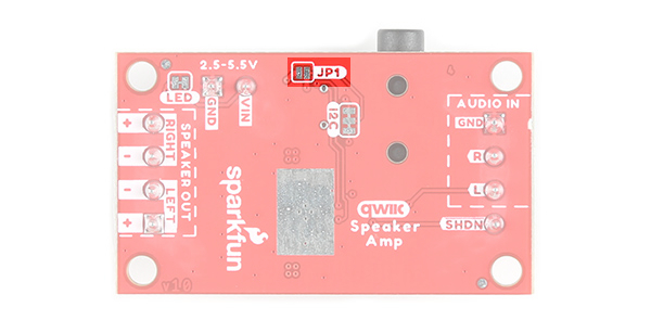
As stated in the Hardware Overview, make sure that the JP1 jumper is soldered if you decide to power the Qwiic Speaker Amp through the Qwiic cable.
Speaker Out
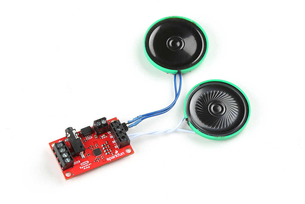
Attach the speaker of your choice to the outputs. For the scope of this tutorial, we will use the 8Ω thin speakers with wires already attached. Connect "+" to "+" and "-" to "-" for both channel. Then tighten down the screws to secure.
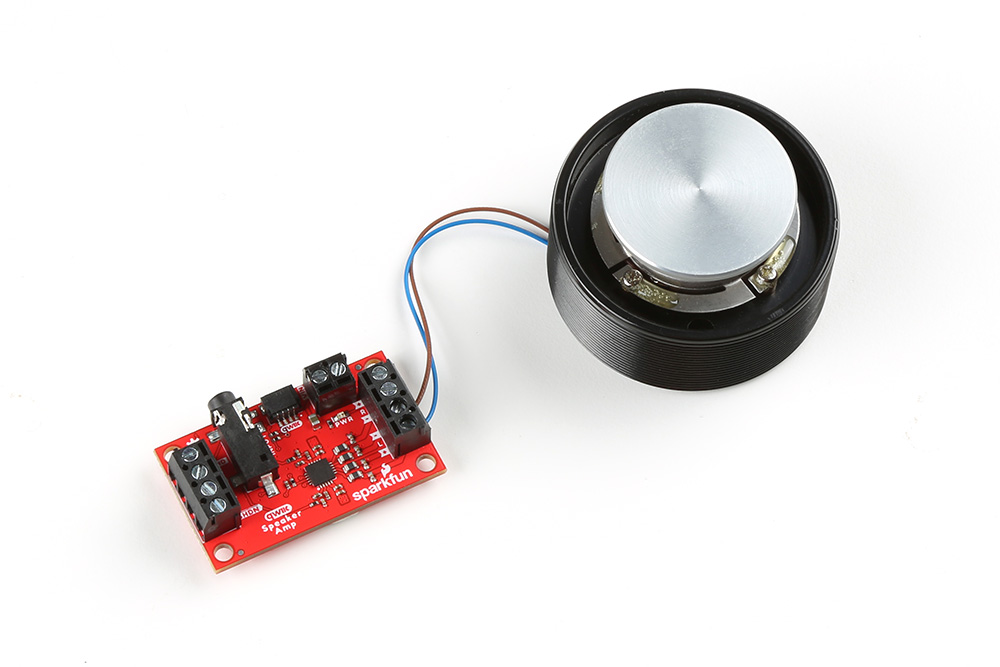
The Qwiic Speaker Amp can also power the 4Ω large surface transducer. While the large surface transducer is rated for 10W, it was still able to make a decent amount of sound when applying it to a surface. The example shown below shows one surface transducer connected to one channel. If you decide to only connect one speaker, make sure to match the connection on the input side as well (i.e. left audio in and left speaker out).
Connecting an Audio Device
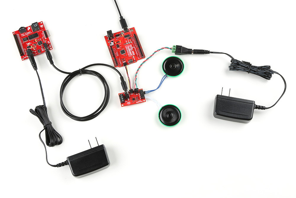
The Qwiic Speaker Amp can operate without an Arduino microcontroller. Simply connect a media player through the TRS connector, speakers, and a power supply to the board. Power up the board and hit play on your favorite track. The Qwiic Speaker Amp will amplify the signal and output it to the speakers using its default settings. Of course, you could also connect an audio board through the screw terminals as explained earlier.

Connecting an Audio Device and Arduino
To control the gain and configure the Qwiic Speaker Amp, you will need an Arduino microcontroller. The setup is pretty much the same as the previous section. However, we connect an Arduino's I2C pins to the Qwiic Speaker Amp's Qwiic connector. You will also need to power the Arduino with a separate power supply. You could use a computer's USB port for programming and power. When you are finished writing your program based on the example code, you could use a 5V USB wall adapter for power.

Depending on your setup, you may need additional power adapter. The example shown below shows the MP3 Trigger with an additional power supply.