Qwiic Scale Hookup Guide
 Nate
Nate 
Hardware Overview
The Qwiic Scale is designed with the NAU7802 IC. This 24-bit analog-to-digital-converter is extremely precise and is designed to read the very small changes in voltage that a load cell or scale produce. SparkFun has carried a similar product, the HX711, for years. The NAU7802 shines in that it has all the great features of the HX711 but uses a true I2C interface allowing the Qwiic Scale to be daisy chained with other sensors and devices on the bus.
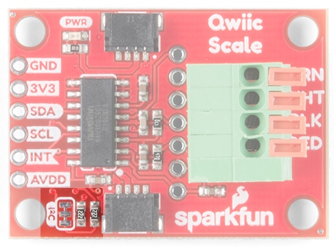
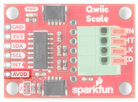
I2C Connections
As we mentioned earlier, two Qwiic connectors allow for easy daisy-chaining but if you prefer to wire in your own I2C connection the pins are available broken out at the edge of the board.
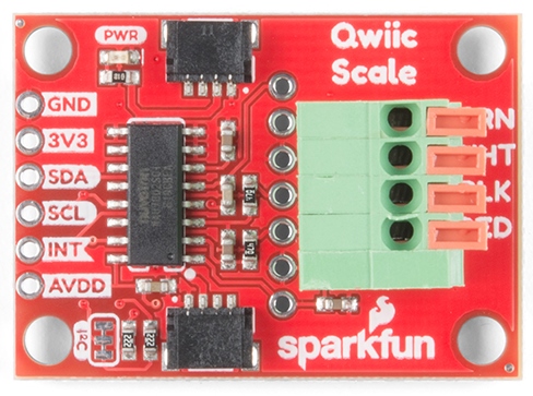
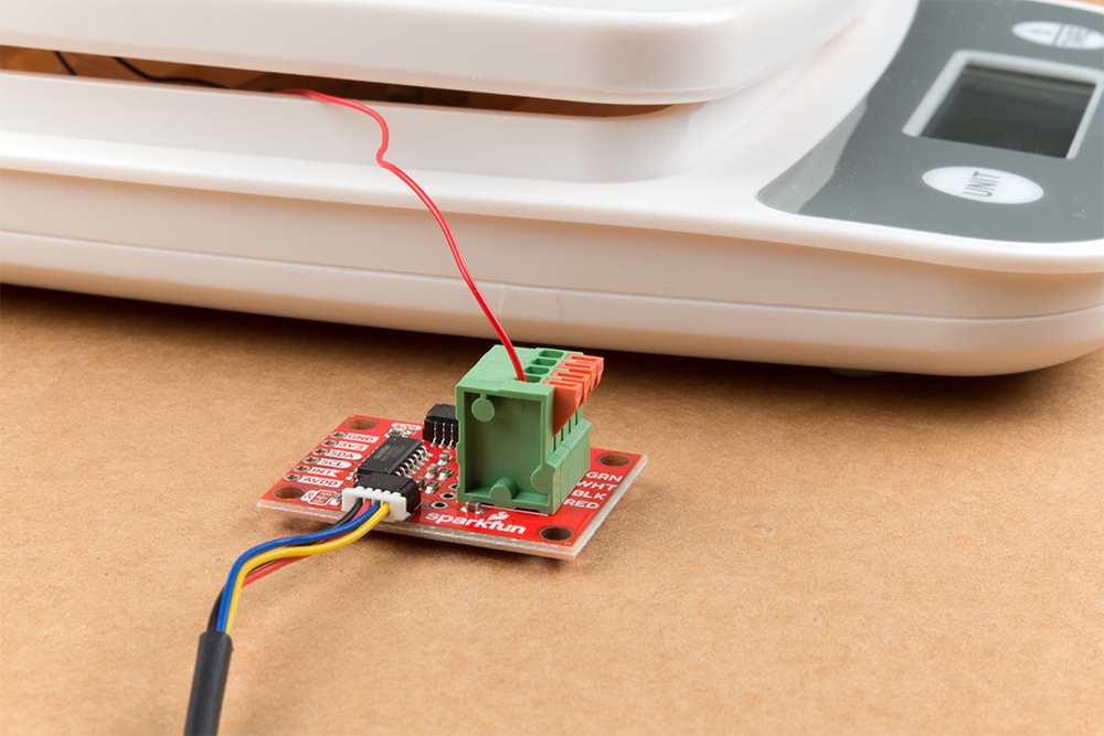
Spring Terminal
A spring terminal is provided to make connecting to a scale possible without soldering. This terminal is operated by depressing the arm and inserting a wire. We found a ball-point pen or a small flat head screwdriver were handy to press one arm down at a time. The terminal can handle 20AWG to 26AWG size wire which is found on nearly all load cells.
There are four silkscreen indicators next to the terminal showing which color wires should be inserted where. These are the ‘standard’ load cell wire colors but may vary slightly between manufacturers. If you’re in doubt, use your best guess and don’t worry - you can’t harm your load cell by wiring it backward!
If the arm returns to level with terminal after inserting the wire then the spring is correctly pinching the wire. If the arm still looks pressed, slightly remove the wire until the terminal pinches on the wire, not the insulation.
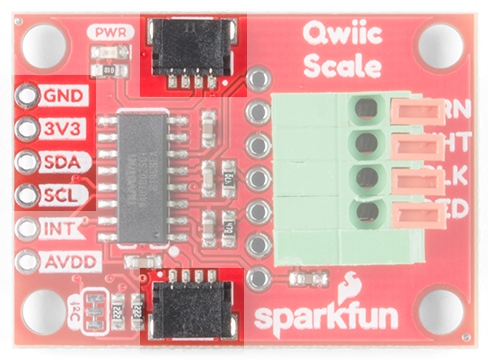
PTH Pins
Additionally, we’ve broken out the ADC and shielding to PTH holes for advanced users. These are helpful if you have a more complex load cell that has shielding around the wires (not required but helps reduce EMI).
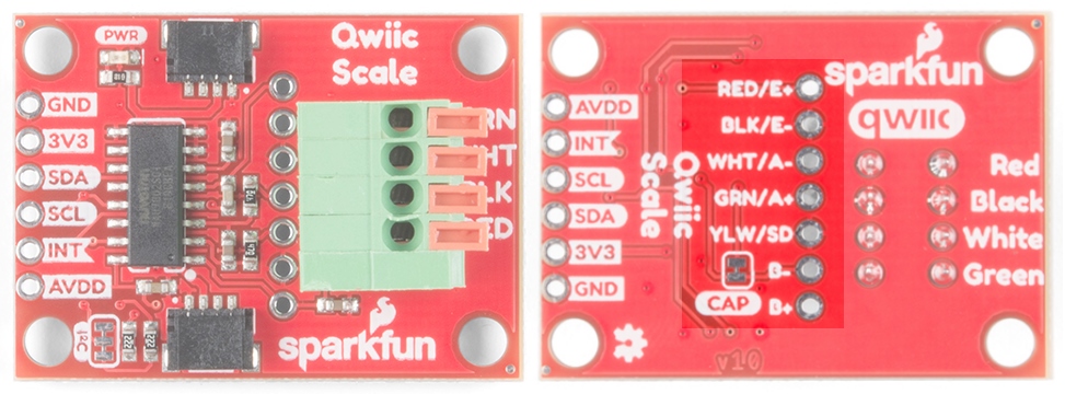
Pin Definitions:
- Red/E+ - Positive voltage of load cell energizing the wheatstone bridge. Most often connected to the red wire of a load cell.
- Black/E- - Negative voltage of the load cell, most often connected to the black wire of a load cell.
- White/A- - Negative branch of the wheatstone bridge, most often connected to the white wire of a load cell.
- Green/A+ - Positive branch of the wheatstone bridge, most often connected to the green wire of a load cell.
- Yellow/Shield - Shield pin for more complex load cells that has shielding around the wire. Sometimes instead of a yellow wire there is a larger black wire, foil, or loose wires to shield the signal wires to lessen EMI. This is not required but helps reduce EMI.
- B- - Called VIN2N in the datasheet. Optional 2nd ADC channel, negative input. This would connect to a 2nd load cell, sharing the E+/E- connections above.
- B+ - Called VIN2P in the datasheet. Optional 2nd ADC channel, positive input. This would connect to a 2nd load cell, sharing the E+/E- connections above.
The NAU7802 is optimized to work with differential pairs meaning load cells and wheatstone bridge type devices. However, it is possible to hook up a regular analog signal between VIN1P with VIN1N connected to ground.
From the datasheet:
This device is optimized to accept differential input signals, but can also measure single-ended signals. When measuring single-ended signals with respect to ground, connect the negative input (VIN1N or VIN2N) to ground and connect the input signal to the positive input (VIN1P or VIN2P). Note that when this device is configured this way, only half of the converter full-scale range is used, since only positive digital output codes are produced.
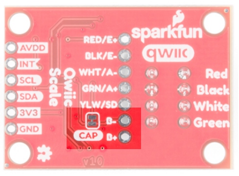
Channel 2
The NAU7802 has a 2nd, optional ADC channel that has a much lower input capacitance (5pF vs 14pF) but is otherwise identical to the 1st channel. By default, this channel has a 330pF capacitor across its inputs. This helps reduce noise on channel one. If you’d like to use the 2nd channel, we recommend removing the capacitor by cutting the CAP jumper. Not sure how to cut a trace? Read here for more information!
Interrupts / Data Ready
By default, the NAU7802 has an interrupt output pin that goes low when a conversion is complete and new data is available to be read. This interrupt can also be configured to go high when new data is available.
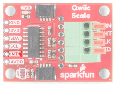
For most applications the interrupt pin is not needed. New data is available at 10, 20, 40, 80, and 320Hz so we can poll the device at regular intervals rather than checking the interrupt pin but it's available for more advanced applications (such as extremely low power projects where the main controller is put to sleep between readings).
AVDD Pin
The NAU7802 has a built-in voltage regulator and will output 4.5V to 2.4V used to bias the load cell. By default, we set AVDD to 3.3V but lowering the bias voltage can be useful for power saving. The AVDD pin is available in case the user wishes to access this voltage as a reference; the AVDD should not be used as a current source. Note that the regulator can only regulate down; you cannot power the board with 3.3V and ask the regulator to output 4.5V.
I2C Jumper
Cutting the I2C jumper will remove the 2.2kΩ resistors from the I2C bus. In general, you shouldn’t need to mess with this jumper. But if you have many devices on your I2C bus, you may want to remove these resistors by cutting the two small traces between the solder pads. Not sure how to cut a jumper? Read here!