Qwiic Scale Hookup Guide
 Nate
Nate Introduction
There are a variety of exciting projects around the measurement of the weight of an object. Whether it measuring if a chicken has left the coup, the bees have left at dawn, or automating the filling of liquids; being able to digitally interface to a scale is key. The Qwiic Scale is an incredibly easy way to read scales and their inner bits, load cells.
We’ve designed the Qwiic Scale so that little or no soldering is required. We’ve even written an Arduino library so that to get the weight of an object it’s as easy as:
language:c
float weight = myScale.getWeight();
Required Materials
If you’re just getting started we recommend obtaining a digital scale and hacking into it. This is because it can be tricky to correctly mechanically attach a load cell.
Alternatively, if you have a unique application, or if this is not your first rodeo measuring weight, checkout the load cells we carry in a variety of shapes and capacities to create your own solution.
We're going to assume you’re just beginning with scales; we recommend you pick out a scale that has roughly the capacity of weight you want to measure. For example, a bathroom scale is best at measuring ~20lbs up to ~300lbs. If you’re trying to measure a few ounces then don’t use a bathroom scale, get a kitchen food scale instead.
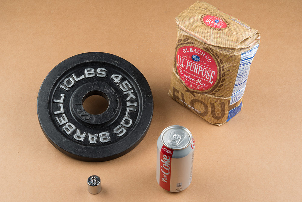
Additionally, you’ll need an item of known weight. This will be used to calibrate your DIY scale. Depending on the accuracy needed for your project, you can use any object (can of soda 394 or 355.1g, dumbell, bag of flour, etc) as long as you know the weight or have an additional scale from which you can get a known weight.
Suggested Reading
If you’re unfamiliar with load cells, jumper pads, or I2C be sure to checkout some of these foundational tutorials.
Analog to Digital Conversion
I2C
Getting Started with Load Cells
How to Work with Jumper Pads and PCB Traces
If you aren't familiar with the Qwiic system, we recommend reading here for an overview.
| Qwiic Connect System |
Hardware Overview
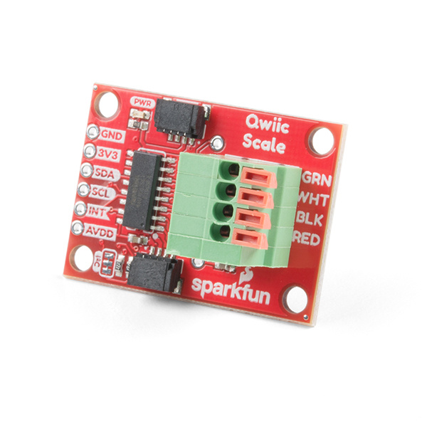
The Qwiic Scale is designed with the NAU7802 IC. This 24-bit analog-to-digital-converter is extremely precise and is designed to read the very small changes in voltage that a load cell or scale produce. SparkFun has carried a similar product, the HX711, for years. The NAU7802 shines in that it has all the great features of the HX711 but uses a true I2C interface allowing the Qwiic Scale to be daisy chained with other sensors and devices on the bus.
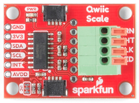
I2C Connections
As we mentioned earlier, two Qwiic connectors allow for easy daisy-chaining but if you prefer to wire in your own I2C connection the pins are available broken out at the edge of the board.
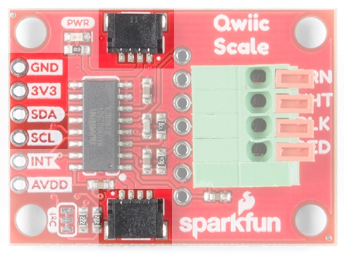
Spring Terminal
A spring terminal is provided to make connecting to a scale possible without soldering. This terminal is operated by depressing the arm and inserting a wire. We found a ball-point pen or a small flat head screwdriver were handy to press one arm down at a time. The terminal can handle 20AWG to 26AWG size wire which is found on nearly all load cells.
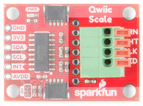
There are four silkscreen indicators next to the terminal showing which color wires should be inserted where. These are the ‘standard’ load cell wire colors but may vary slightly between manufacturers. If you’re in doubt, use your best guess and don’t worry - you can’t harm your load cell by wiring it backward!
If the arm returns to level with terminal after inserting the wire then the spring is correctly pinching the wire. If the arm still looks pressed, slightly remove the wire until the terminal pinches on the wire, not the insulation.
PTH Pins
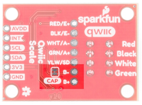
Additionally, we’ve broken out the ADC and shielding to PTH holes for advanced users. These are helpful if you have a more complex load cell that has shielding around the wires (not required but helps reduce EMI).
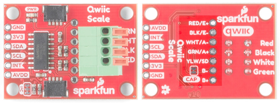
Pin Definitions:
- Red/E+ - Positive voltage of load cell energizing the wheatstone bridge. Most often connected to the red wire of a load cell.
- Black/E- - Negative voltage of the load cell, most often connected to the black wire of a load cell.
- White/A- - Negative branch of the wheatstone bridge, most often connected to the white wire of a load cell.
- Green/A+ - Positive branch of the wheatstone bridge, most often connected to the green wire of a load cell.
- Yellow/Shield - Shield pin for more complex load cells that has shielding around the wire. Sometimes instead of a yellow wire there is a larger black wire, foil, or loose wires to shield the signal wires to lessen EMI. This is not required but helps reduce EMI.
- B- - Called VIN2N in the datasheet. Optional 2nd ADC channel, negative input. This would connect to a 2nd load cell, sharing the E+/E- connections above.
- B+ - Called VIN2P in the datasheet. Optional 2nd ADC channel, positive input. This would connect to a 2nd load cell, sharing the E+/E- connections above.
The NAU7802 is optimized to work with differential pairs meaning load cells and wheatstone bridge type devices. However, it is possible to hook up a regular analog signal between VIN1P with VIN1N connected to ground.
From the datasheet:
This device is optimized to accept differential input signals, but can also measure single-ended signals. When measuring single-ended signals with respect to ground, connect the negative input (VIN1N or VIN2N) to ground and connect the input signal to the positive input (VIN1P or VIN2P). Note that when this device is configured this way, only half of the converter full-scale range is used, since only positive digital output codes are produced.
Channel 2
The NAU7802 has a 2nd, optional ADC channel that has a much lower input capacitance (5pF vs 14pF) but is otherwise identical to the 1st channel. By default, this channel has a 330pF capacitor across its inputs. This helps reduce noise on channel one. If you’d like to use the 2nd channel, we recommend removing the capacitor by cutting the CAP jumper. Not sure how to cut a trace? Read here for more information!
Interrupts / Data Ready
By default, the NAU7802 has an interrupt output pin that goes low when a conversion is complete and new data is available to be read. This interrupt can also be configured to go high when new data is available.
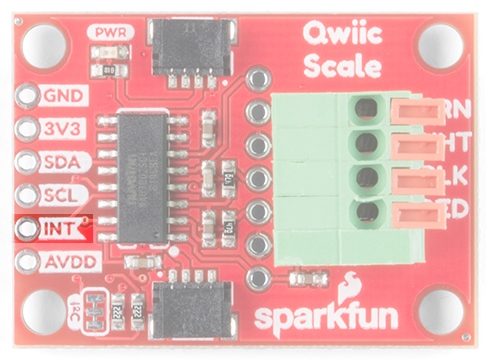
For most applications the interrupt pin is not needed. New data is available at 10, 20, 40, 80, and 320Hz so we can poll the device at regular intervals rather than checking the interrupt pin but it's available for more advanced applications (such as extremely low power projects where the main controller is put to sleep between readings).
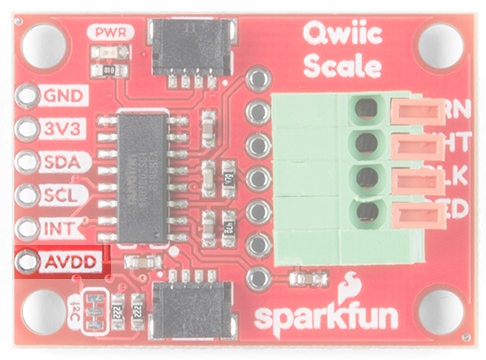
AVDD Pin
The NAU7802 has a built-in voltage regulator and will output 4.5V to 2.4V used to bias the load cell. By default, we set AVDD to 3.3V but lowering the bias voltage can be useful for power saving. The AVDD pin is available in case the user wishes to access this voltage as a reference; the AVDD should not be used as a current source. Note that the regulator can only regulate down; you cannot power the board with 3.3V and ask the regulator to output 4.5V.
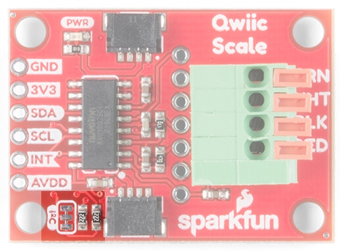
I2C Jumper
Cutting the I2C jumper will remove the 2.2kΩ resistors from the I2C bus. In general, you shouldn’t need to mess with this jumper. But if you have many devices on your I2C bus, you may want to remove these resistors by cutting the two small traces between the solder pads. Not sure how to cut a jumper? Read here!
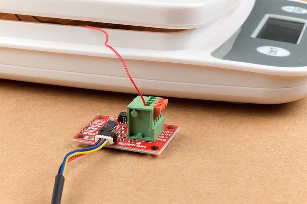
Hardware Assembly
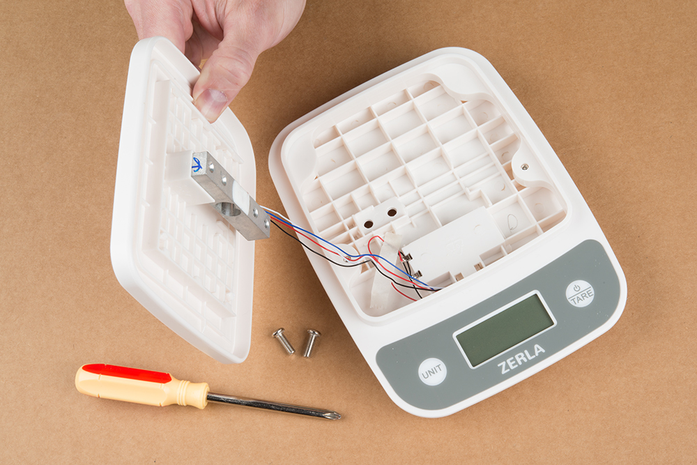
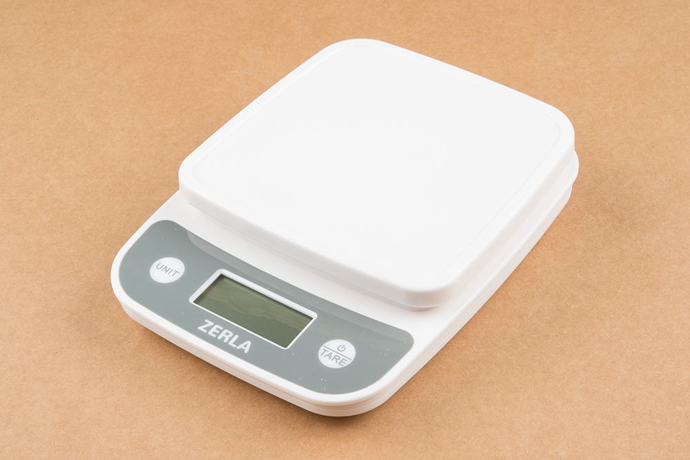
Below we disassemble a small kitchen scale with a common load cell to demonstrate how to attach the Qwiic Scale. Modifying a bathroom scale (for larger maximum weight) with four individual point load cells is possible but requires the routing of many more wires. We recommend a scale with a bar type load cell (most kitchen scales have this) for your first Qwiic Scale project.
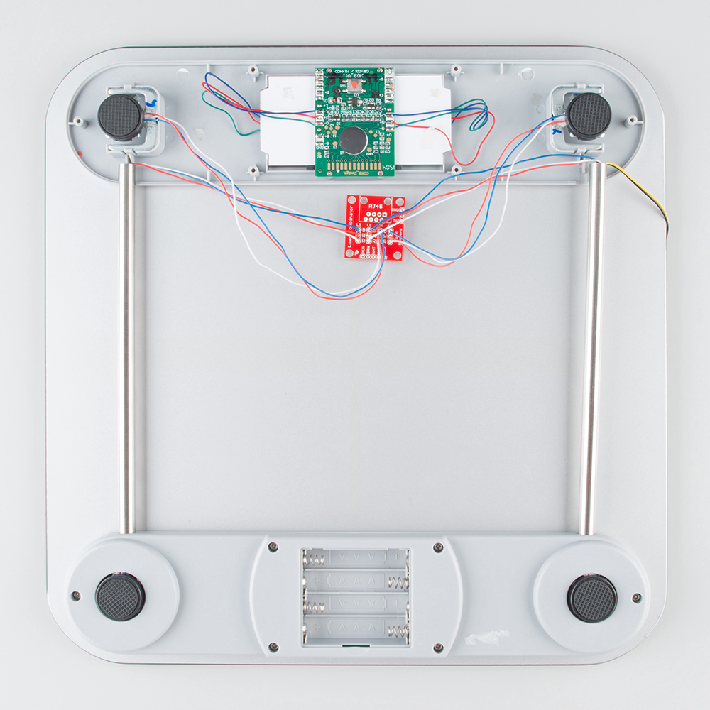
Remove any sticker and cover to get access to two screws that secure the bar load cell to the floating platform.

This will release the platform from the base. Note the four wires connecting the load cell to the front area of electronics.
Most load cells have four wires colored red, black, white, and green. If your load cell doesn’t, that’s ok! Checkout our troubleshooting section for how to suss out the correct connection.

Are you hacking into a bathroom scale? These often use four individual cells that need to be combined into one complete load cell. We created the Load Cell Combinator to make this a lot easier. Once you have your combinator in place, you should have the four wires (Red, Black, White, Green) coming out of the combinator ready to connect to Qwiic Scale.
If you are hacking into a kitchen scale or load cell with wires that are not stripped, use a pair of wire strippers to remove about ¼” of insulation.
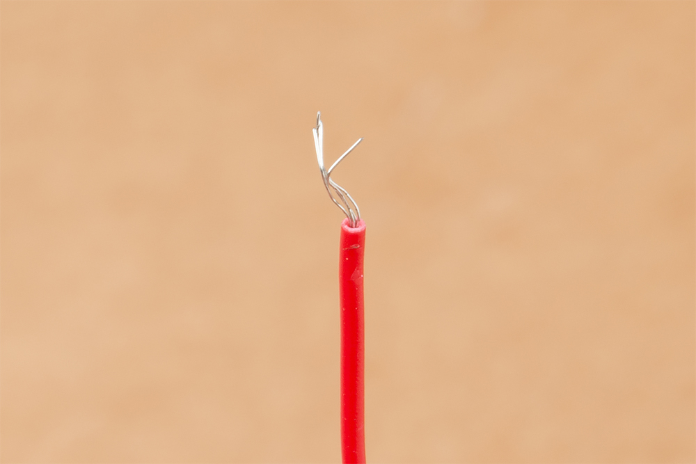
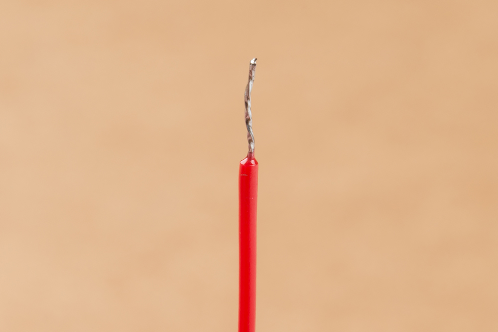
Most load cells have stranded wire as opposed to solid core. Stranded wire helps reduce breaking wires when bent back and forth. The down side to stranded wire is that it tends to go everywhere when you try to insert it into a hole such as the spring terminal on Qwiic Scale. Before trying to insert the wire give the end a few twists with your fingers to get all the wires bent back together.
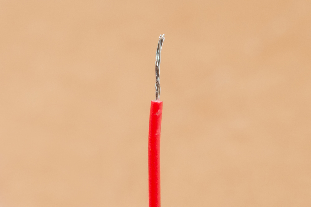
For extra points, after you’ve twisted the end of the wire hit it with a dab of molten solder - this will lock the wires into place. This is called 'tinning' and helps a lot when working with stranded wire but is not required.
Now insert the first red wire into the spring terminal. If the arm returns to level with terminal, then the terminal is correctly pinching the wire. Give the wire a very light tug - it should hold in place.
If the arm is slightly depressed that means the wire has been inserted too deep and the terminal is pinching on the insulation around the wire. Press on the arm again and pull the wire slightly out until you hit the soft spot where the terminal pinches on wire, not the insulation.
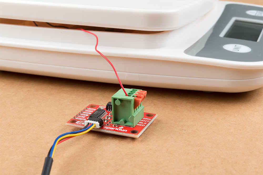
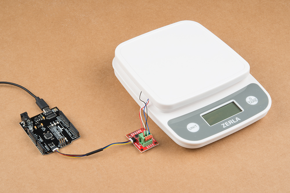
Insert all four wires according to the color of wire and the silkscreen indicator on the Qwiic Scale PCB. Now attach Qwiic Scale to your RedBoard using a Qwiic cable or other microcontroller with a Qwiic Breadboard Cable. You're ready to start coding!
Qwiic Scale Arduino Library and Overview
The SparkFun Qwiic Scale NAU7802 Arduino Library is a fully featured library for reading weights as well as configuring the IC. We recommend you install the library via the Arduino IDE by using the library manager and search for SparkFun Scale. Or you can download and manually install a zip of the library by clicking on the link below. For those who want to view the code, check out the GitHub repo.
Once you have the library installed we recommend you start with Example1 and advance through the examples as you go. You do not need to read or absorb all the following functions, they are demonstrated and described in the examples. But if you're really advanced and just want the available functions, here they are:
bool begin(TwoWire &wirePort = Wire)- Check communication and initialize sensor. Returns true if sensor is successfully started. Optionally, you can pass in a different Wire port.bool isConnected()- Returns true if device acknowledges a call to its I2C address.bool available()- Returns true if Cycle Ready bit is set (conversion is complete).int32_t getReading()- Returns 24-bit reading. Assumes CR Cycle Ready bit (ADC conversion complete) has been checked by.available().int32_t getAverage(uint8_t samplesToTake)- Return the average of a given number of readings.void calculateZeroOffset(uint8_t averageAmount = 8)- Also called taring. Call this with nothing on the scale.void setZeroOffset(int32_t newZeroOffset)- Sets the internal variable. Useful for users who are loading values from NVM.int32_t getZeroOffset()- Ask library for the zero offset value. Useful for storing value into NVM.void calculateCalibrationFactor(float weightOnScale, uint8_t averageAmount = 8)- Call this with the value of the thing on the scale. Sets the calibration factor based on the weight on scale and zero offset.void setCalibrationFactor(float calFactor)- Pass a known calibration factor into library. Helpful when loading settings from NVM.float getCalibrationFactor()- Ask library for the calibration factor. Useful for storing value into NVM.float getWeight(bool allowNegativeWeights = false)- Once you've set zero offset and cal factor, you can ask the library to do the calculations for you. By default, negative weights will be returned as 0.bool setGain(uint8_t gainValue)- Set the gain by callingmyScale.setGain(NAU7802_GAIN_16). x1, 2, 4, 8, 16, 32, 64, 128 are available.bool setLDO(uint8_t ldoValue)- Set the onboard Low-Drop-Out voltage regulator to a given value by callingmyScale.setLDO(NAU7802_LDO_3V6). 2.4, 2.7, 3.0, 3.3, 3.6, 3.9, 4.2, 4.5V are available.bool setSampleRate(uint8_t rate)- Set the readings per second by callingmyScale.setSampleRate(NAU7802_SPS_80). 10, 20, 40, 80, and 320 samples per second is available.bool setChannel(uint8_t channelNumber)- Select between 1 and 2bool calibrateAFE()- Calibrate the analog front end of the IC. This function is unrelated to setting the zero offset and calibration factor and should rarely be used. It is recommended that the AFE be re-calibrated any time the gain, SPS, or channel number is changed. Returns true if CAL_ERR bit is 0 (no error).bool reset()- Resets all registers to Power On Defaultsbool powerUp()- Power up digital and analog sections of scale, ~2mAbool powerDown()- Puts scale into low-power 200nA modebool setIntPolarityHigh()- Set Int pin to be high when data is ready (default)bool setIntPolarityLow()- Set Int pin to be low when data is readyuint8_t getRevisionCode()- Get the revision code of this IC. Always 0x0F.
Here are the lower level functions to manipulate registers:
bool setBit(uint8_t bitNumber, uint8_t registerAddress)- Mask & set a given bit within a registerbool clearBit(uint8_t bitNumber, uint8_t registerAddress)- Mask & clear a given bit within a registerbool getBit(uint8_t bitNumber, uint8_t registerAddress)- Return a given bit within a registeruint8_t getRegister(uint8_t registerAddress)- Get contents of a registerbool setRegister(uint8_t registerAddress, uint8_t value)- Send a given value to be written to given address. Return true if successful.
Examples
The following examples highlighted from the library will show the readings on a serial monitor.
Example 1: Basic Readings
Example 1 will show you basic output from the NAU7802. This is helpful for getting the basic hardware setup. If you've got everything wired up correctly than the value should change by thousands or hundreds of thousands as you press on your scale.
Example 2: Complete Scale
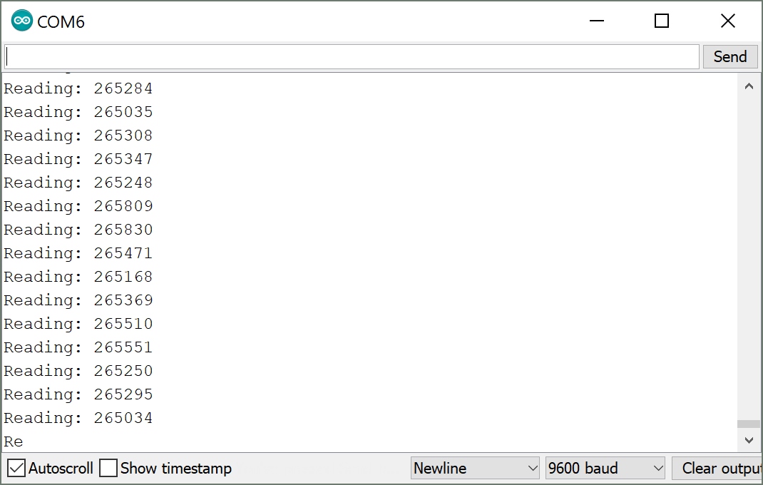
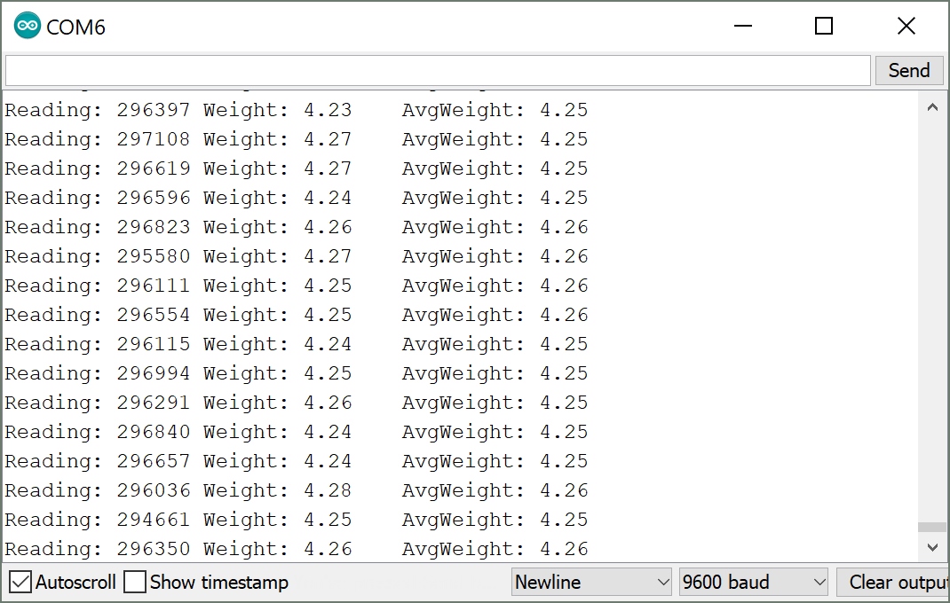
Example 2 is where it starts to get interesting. This example will show you how to characterize your scale. You’ll need a scale fully setup and calibrated with a a known weight (like a dumbbell or can of soda). If you have not calibrated the scale, you'll need to send a c in the serial terminal and follow the prompts to calibrate the scale. After calibration and reuploading the code to your Arduino, you should see an output similar to the reading below.
Advanced Examples
We included additional examples in the library demonstrating how to change the gain, sample rate, as well as how to shut the IC down for low-power projects. For platforms that have multiple Wire ports (i.e. Teensy, not Uno), we also offer an AdvancedI2C example showing how to point the library to use Wire1.
How to Characterize Your Scale
You should have your scale hooked up, but there's one more step before we get measuring. It's time to teach your scale how much one thing weighs so it can tell how much everything else weighs!
Load cells have a linear response meaning their value changes in proportion to the force or weight applied to it. Remember the y = mx + b stuff you learned in school? It’s ok if you didn’t! The characterization of a scale looks like this:
- Hookup the scale and get the Example1_BasicReadings.ino outputting a good, changing value.
- Load Example2_CompleteScale.ino
- Take everything off your scale and press ‘c’ to get a ‘zero’ reading
- Place a known weight (can of soda, weight lifting plate, etc) on your scale and enter its value. For example, if you placed a 150 gram weight on your scale, enter 150.0.
That’s it. You can remove the known weight and weigh anything else you have lying around. But what’s really going on?
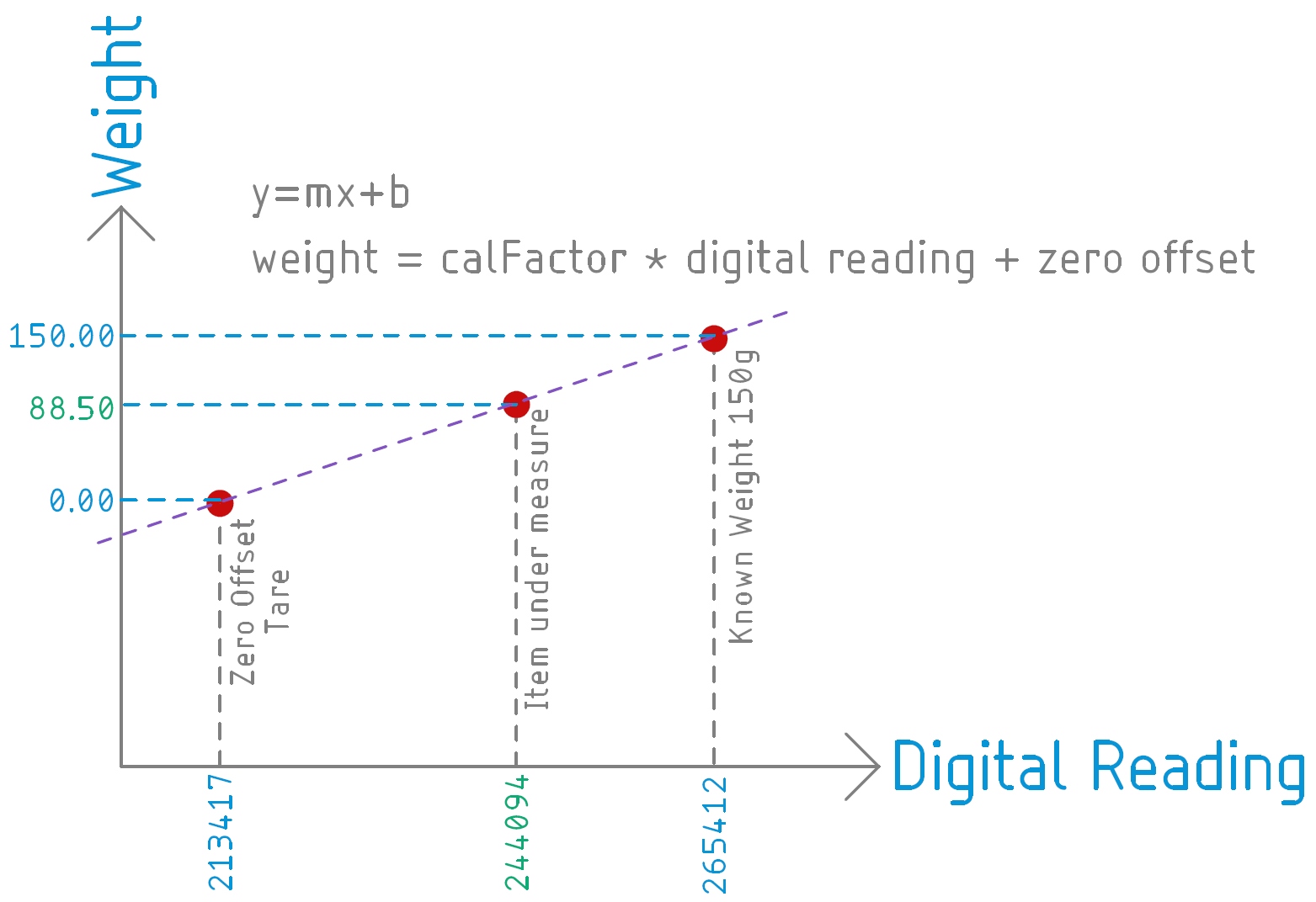
Instead of y = mx + b imagine weight = calibrationFactor * reading + zeroOffset.
The SparkFun library for the NAU7802 takes digital readings. These readings will vary from 10,000 to over 1 million. These values are unitless - the IC doesn’t know if there’s grams or lbs or stones on your scale, all it knows is the change in value. So when you remove all weight from your scale, there’s still a non-zero value being measured. We call this the zero offset (also known as the +b portion of the y = mx + b) and it’s set when you call the calculateZeroOffset() function. When you place a known weight on the scale and call the calculateCalibrationFactor(150.0) function the library will do the following math (and set the m portion of y=mx+b).
Let's say you measured 213417 with nothing on the scale. Once you added 150grams the scale measured 265412. From these numbers we can calculate the slope of the line:
language:latex
Zero offset = 213417
Calibration factor = (265412 - 213417) / 150 = 346.6333
We now know that for every change of 346 in the digital reading we are seeing a change of 1 gram. NEAT.
Now, whatever we put on the scale we can get its weight by extrapolating between the zero offset and the known weight. For example, if we put an unknown thing on the scale and get a reading of 244094 we know:
language:latex
244094 - 213417 = 30677

30677 / 346.633 = 88.4999
88.5 grams! Again, these values are unitless but as long as you know that the known weight was in grams, then the ‘weight’ is output in grams.
getZeroOffset() and getCalibrationFactor() functions. Once obtained, store these values in EEPROM or other NVM. This will allow you to create a scale that can power up, load the values from NVM and immediately begin measuring weight. When power cycling your system you’ll want to reload them with the setZeroOffset(213417) and setCalibrationFactor(346.6333) functions. This is demonstrated in Example2.
FAQ and Troubleshooting
The Full Scale Example Never Changes from Zero.
Are you seeing something like this? Where the readings are changing but the weight doesn't?
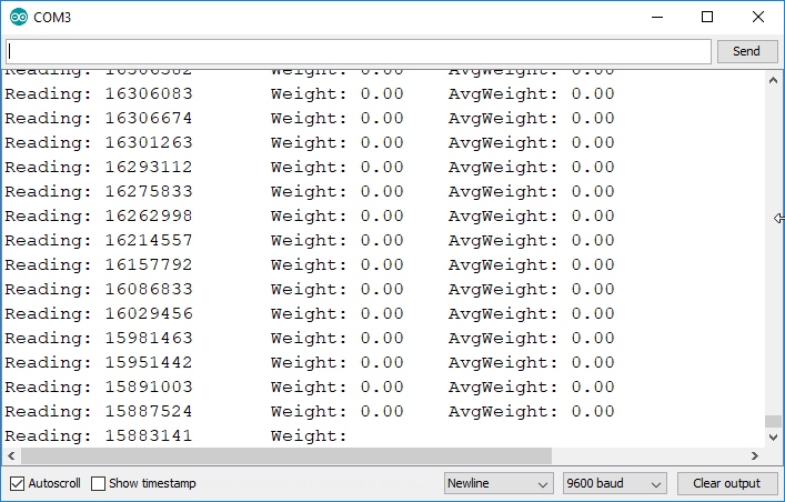
If you see the readings are decreasing when you press on the scale, then the A+/A- wires are probably backwards. Because the readings go down with more weight, the displayed weight will never go above zero. Try reversing the white and green wires.
The Values Decreasing When I Push Down on the Load Cell! Help!
A+/A- wires are probably backwards. Try reversing the white and green wires.
Example1 Displays Constant Values ~1000 / ~8,000,000 / ~ 16,000,000 / The Scale Doesn’t Work
More than likely you have a wire that is not making contact. Be sure to insert the stripped wire into the spring terminal but not too far. If the terminal is ‘pinching’ on the insulation rather than the wire then it will not make an electrical connection. Press down on the arm and pull the wire out a few millimeters.
Can I Measure 0.001 Grams?
Probably not. Really high precision scales don't use load cells for a variety of reasons. Check out 'weight scale elements' which are basically a balance scale that uses an electromagnet and a PID loop.
We were able to reliably and accurately measure a change of 5 grams on a 10kg max load cell, or 0.05%. So on a 200kg load cell that’s 100 grams. On a smaller 100g max load cell you may be able to reliably measure down to 50 milligrams.
Here are some things to consider as you get into finer accuracy measurements:
- Temperature variations in the load cell will change the zero offset and known weight values. You’ll need to recharacterize your scale if the temperature swings more than a couple degrees Celsius.
- For milli and micro gram readings, professional scales will often have a air cover reducing the effects of small currents in the environment.
- Vibrations from HVAC equipment, trains, etc can affect readings.
The Wire Colors on My Load Cell Don’t Match Anything Here!
Never fear. Disconnect the wires from Qwiic Scale and use a multimeter to measure the resistance between each wire. Take notes as you go. Start with one wire and find the lowest resistance to two others. You now know this wire falls in between the other two in the wheatstone bridge shown below.

Once you have the pairs of wires identified (possible VCC/GND pair and A+/A- pair) then attach those pairs to Qwiic Scale. If the readings go down when you press on the scale, then you’ve got A+/A- reversed. If the scale doesn’t work at all then swap the pairs so that your assumed VCC/GND move into A+/A- and vice versa.
My 1000kg Load Cell is Acting Oddly.
By default, the library sets the gain to the maximum of 128 because most of our users are measuring smaller load cells. If you’re measuring very large weights, you may need to reduce the gain by using the following command:
language:c
myScale.setGain(NAU7802_GAIN_16);
Gains of 1, 2, 4, 8, 16, 32, 64, and 128 are available.
How Much Does a Can of Soda Weigh?
I’m glad you asked because it’s fascinating that it changes between regular (394g) and diet (355.1g). Read all about it from the Virtual Chembook:
Resources and Going Further
We hope you’ve enjoyed learning about Qwiic Scale and Load Cells in general. For more information, check out the resources below:
- Schematic
- Eagle Files
- NAU7802 Datasheet
- Repo for the latest files:
- SFE Product Showcase
Be sure to checkout the hookup guides for other Qwiic devices to see how easy it is to measure and control the world!