Qwiic Pressure Sensor (BMP581) Hookup Guide
Introduction
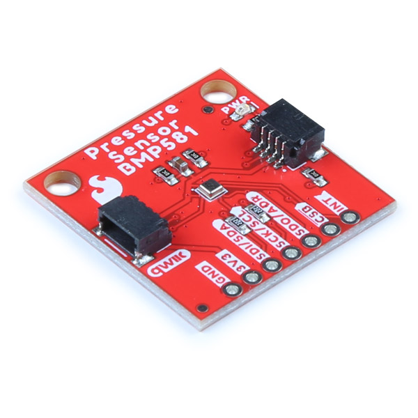
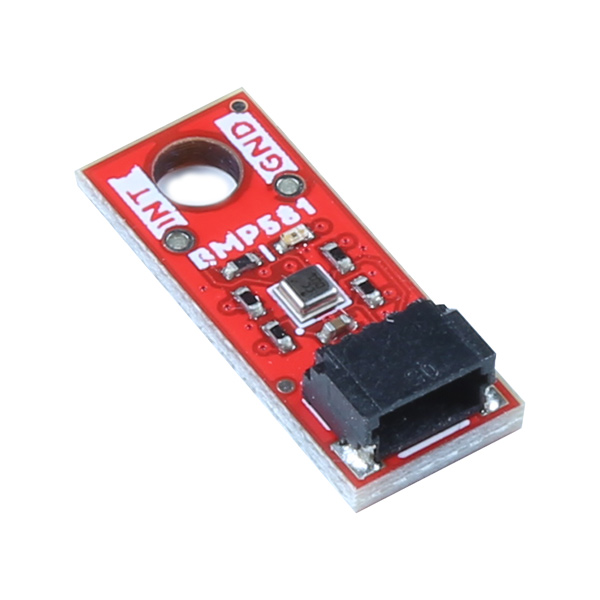
The SparkFun Pressure Sensor - BMP581 (Qwiic) and Micro Pressure Sensor - BMP581 (Qwiic) feature the BMP581 absolute pressure sensor from Bosch Sensortec. The BMP581 boasts exceptional resolution and accuracy and uses on-chip linearization and temperature compensation to provide true absolute data for pressure and temperature.
This guide will take you through the hardware present on these Qwiic breakouts, connecting them to a Qwiic circuit and using the BMP581 with the SparkFun BMP581 Arduino Library.
Required Materials
To follow along with this guide you will need a microcontroller to communicate with the BMP581. Below are a few options that come Qwiic-enabled out of the box:
If your chosen microcontroller is not already Qwiic-enabled, you can add that functionality with one or more of the following items:
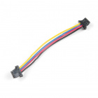
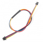
You will also need at least one Qwiic cable to connect your sensor to your microcontroller.
Qwiic Cable - 100mm
PRT-14427Qwiic Cable - 50mm
PRT-14426Qwiic Cable - 200mm
PRT-14428Qwiic Cable - 500mm
PRT-14429Recommended Reading
If you aren't familiar with the Qwiic system, we recommend reading here for an overview.
 |
We would also recommend taking a look at the following tutorials if you aren't familiar with them. If you are using one of the Qwiic Shields listed above, you may want to read through their respective Hookup Guides as well before going through this guide for this BMP581 Qwiic breakout.
I2C
Serial Terminal Basics
Qwiic Shield for Arduino & Photon Hookup Guide
SparkFun Qwiic Shield for Arduino Nano Hookup Guide
Hardware Overview
In this section we'll take a closer look at the hardware present on these Qwiic Pressure Sensor - BMP581 breakouts.
BMP581 Pressure Sensor
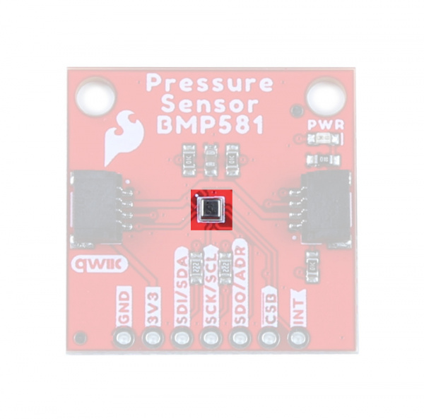
The BMP581 is an extremely precise and versatile absolute pressure sensor from Bosch Sensortec that uses on-chip linearization and temperature compensation to provide true absolute pressure and temperature data.
 |
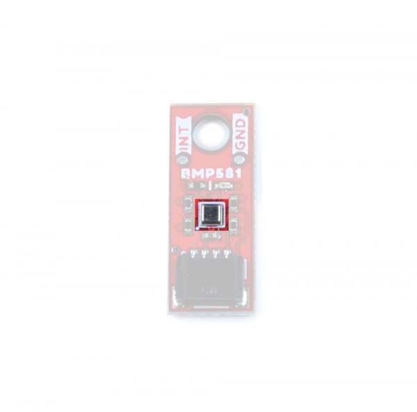 |
The BMP581 features a wide pressure sensing range (30 to 125 kPa), pressure data resolution of 1/64 Pa with excellent accuracy across the sensing range (± 0.5 hPa (max)) as well as output data rates up to 622 Hz. All of this in a package size of just 2.0 mm2!
The sensor accepts a supply voltage of 1.71V to 3.6V though the board runs the sensor at 3.3V. The BMP581 includes a FIFO buffer that can store up to 32 samples, user-programmable low-pass filtering as well as configurable IIR settings to help offset noise created by ambient changes in pressure such as doors/windows opening or closing or wind passing by the sensor. Lastly, the BMP581 even has 6 bytes of user-programmable non-volatile memory.
The table below outlines some of the BMP581's sensing parameters. For a full overview of the BMP581, refer to the datasheet.
| Parameter | Min. | Typ. | Max. | Units | Notes |
|---|---|---|---|---|---|
| Operating Temperature | -40 | 25 | 85 | °C | |
| Operating Pressure | 30 | - | 125 | kPa | |
| Relative Accuracy | - | ±0.06 | - | hPa | Per 10 kPa step. |
| Absolute Accuracy | - | - | ±0.5 | hPa | |
| Temp. Coeff. Offset | - | ±0.5 | - | Pa/K | At 900hPa & 25-40°C |
| Pressure Noise1 | - | 0.78 | .095 | PaRMS | Oversampling rate set to "Lowest Power". |
| - | 0.21 | 0.25 | PaRMS | Oversampling rate set to "High Resolution". | |
| - | 0.08 | PaRMS | Oversampling rate set to "Highest Resolution". | ||
| Output Data Rate 1 | 0.125 | - | 240 | Hz | Range is for Normal Mode. |
The sensor has seven operating modes outlined in the table below. For complete information on the power modes and configuration settings available or required for them, refer to section 4.3 of the datasheet:
| Operating Mode | Power Consumption (@25°C and VDDIO/VDD=3.3V) | Notes |
|---|---|---|
| Standby | 1.0µA (.typ) | Saves the last pressure/temperature values measured as well as FIFO data (if enabled). |
| Deep Standby | 0.55µA (typ.) | Most efficient power consumption. Entering Deep Standby requires a specific set of conditions. Refer to section 4.3.2 of the datasheet for more information. |
| Forced | Single-shot measurements taken according to measurement and filter options. Sensor returns to sleep mode. Measurements available for reading on the data registers. Must return sensor to forced mode for next measurement. | |
| Normal | 260µA (max) | Sensor performs measurements on a configured frequency set as the Output Data Rate (ODR). The sensor cycles between active measurements and standby periods. |
| Low Power Normal | 1.3µA (typ.) | Operates the same as Normal Mode but enters Deep Standby mode in between measurement periods. |
| Continuous | 260µA (max) | Sensor performs measurements at the maximum frequency possible with the selected oversampling settings. Sensor remains in the active measurement with no cycling to a standby period. |
| Sleep | The sensor must be put into Sleep Mode when transitioning between any of the operating modes. |
Communication Interfaces - I2C & SPI
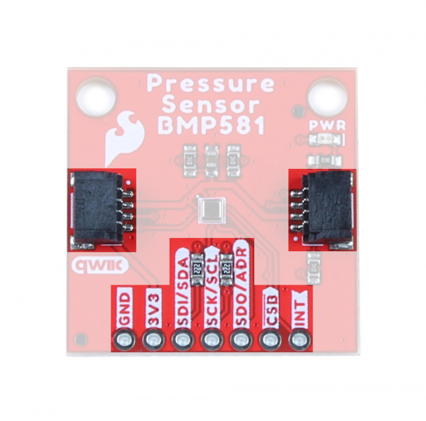
The standard size Qwiic Pressure Sensor (BMP581) communicates over I2C by default but also supports using the BMP581 over SPI. The Qwiic Micro version only supports I2C over the Qwiic connector on the board.
 |
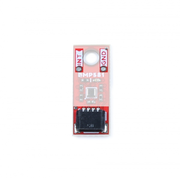 |
The breakout routes the I2C interface to a pair of Qwiic connectors as well as a 0.1"-spaced PTH header for users who prefer a traditional, soldered connection. This PTH header shares the SPI connections and also includes the Interrupt pin.
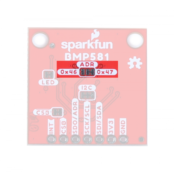
The board sets the BMP581's I2C address to 0x47 by default. Adjust the ADR jumper to change to the alternate address (0x46) or leave it completely open to use the SPI interface (Standard size only). More information on this jumper in the Solder Jumpers section below.
Solder Jumpers
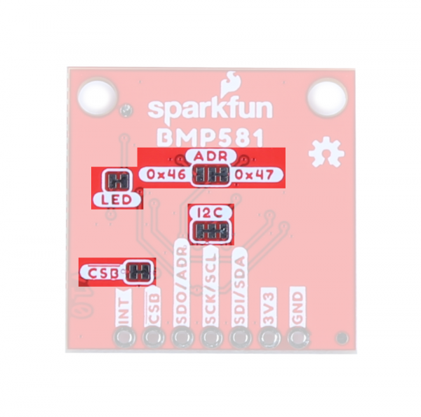
The standard size breakout has four solder jumpers labeled: I2C, ADR, CSB and LED. The micro size breakout has all but the CSB jumper since the micro version does not support SPI.
 |
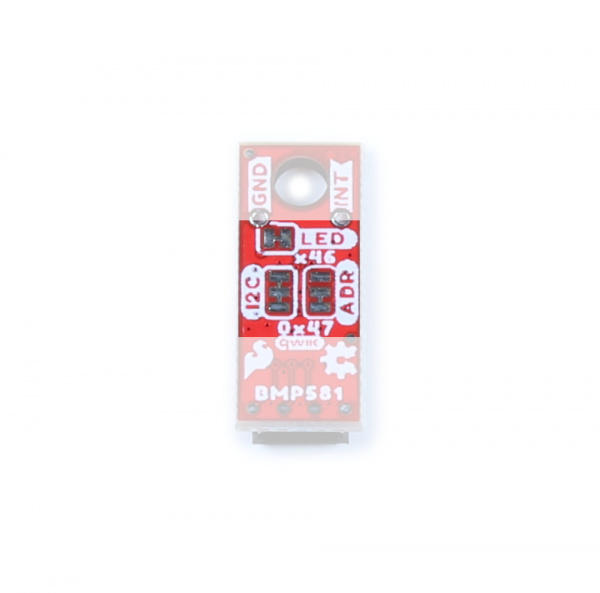 |
The I2C jumper connects a pair of 2.2kΩ resistors to the SDA/SCL lines. Leave these enabled unless you have a large number of I2C devices on the same bus.
The ADR jumper sets the I2C address of the BMP581 to 0x47 by default (0x46 alternate). It also controls whether it operates via I2C or SPI. Open the jumper completely to set the BMP581 to communicate via SPI.
The CSB jumper pulls the Chip Select pin to VDD (3.3V) through a 10kΩ resistor. Open the jumper to disable the pullup.
The LED jumper completes the Power LED circuit. Open the jumper to disable the Power LED if desired.
Board Dimensions
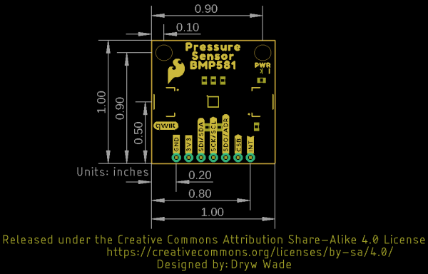
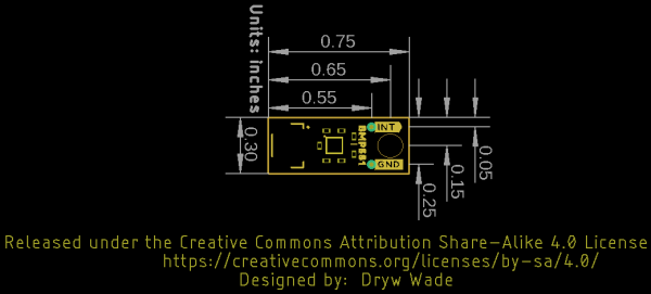
The standard size Qwiic breakout matches the 1.0" x 1.0" (25.4mm x 25.4mm) form factor for Qwiic breakouts with two mounting holes that fit a size 4-40 screw. The Micro version of this breakout matches the Qwiic Micro form factor and measures 0.75" x 0.30" (24.65mm x 7.62mm) and has one mounting hole that fits a size 4-40 screw.
 |
 |
Hardware Assembly
Now that we're familiar with the Qwiic Pressure Sensor (BMP581), we can start assembling our circuit.
Qwiic/I2C Assembly
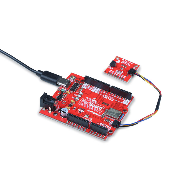
The fastest and easiest way to get started using the breakout is to connect the Qwiic connector on the breakout to a Qwiic-enabled development board like the SparkFun RedBoard Artemis with a Qwiic cable and as shown in the image below.
If you would prefer a more secure and permanent connection with the Standard size version, you can solder headers or wire to the PTH header on the board.
SPI Assembly (Standard Size Only)
Setting the breakout up to communicate with the sensor over SPI requires completely opening the ADR jumper and we recommend soldering to the PTH header to make the connections. If you are not familiar with through-hole soldering, take a read through this tutorial:
How to Solder: Through-Hole Soldering
Along with tools for soldering, you'll need either some hookup wire or headers and jumper wires. Sever the trace between the "Center" and "Right" pads of the ADR jumper to tell the BMP581 to communicate using SPI. After opening this jumper, connect the BMP581 to your controller's SPI pins.
Remember, the BMP581 operates at 3.3V logic so make sure to connect to a board running at the same logic level like the RedBoard Artemis or use a level shifter to adjust it to a safe voltage.
SparkFun BMP581 Arduino Library
Note: This library assumes you are using the latest version of the Arduino IDE on your desktop. If this is your first time using Arduino, please review our tutorial on installing the Arduino IDE. If you have not previously installed an Arduino library, please check out our installation guide.
The SparkFun BMP581 Arduino Library is based off the API for the sensor from Bosch. Install the library through the Arduino Library Manager tool by searching for "SparkFun BMP581". Users who prefer to manually install the library can download a copy of it from the GitHub repository by clicking the button below:
Library Functions
The list below outlines and describes the functions available in the SparkFun BMP581 Library:
int8_t beginI2C(uint8_t address = BMP581_I2C_ADDRESS_DEFAULT, TwoWire& wirePort = Wire);- Initialize the BMP581 at the default I2C address on the specified Wire port.int8_t beginSPI(uint8_t csPin, uint32_t clockFrequency = 100000);- Initialize the BMP581 over SPI using the defined Chip Select pin and set clock frequency (default 100kHz).int8_t init();- Initialize the BMP581 sensor. The begin function handles this automatically.int8_t setMode(bmp5_powermode mode);- Set the operating mode. Valid options are: . The begin function handles this automatically.int8_t getMode(bmp5_powermode* mode);- Returns the value set for the operating mode.int8_t enablePress(uint8_t pressEnable);- Enable pressure and temperature sensing. The begin function handles this automatically.
Sensor Data and Settings
int8_t getSensorData(bmp5_sensor_data* data);- Pulls pressure and temperature data from the sensor.int8_t setODRFrequency(uint8_t odr);- Set the output data rate frequency.int8_t getODRFrequency(uint8_t* odr);- Returns the value set for the output data rate frequencyint8_t setOSRMultipliers(bmp5_osr_odr_press_config* config);- Set the oversampling multiplier.int8_t getOSRMultipliers(bmp5_osr_odr_press_config* config);- Returns the value stored for the oversampling multiplier.int8_t getOSREffective(bmp5_osr_odr_eff* osrOdrEffective);int8_t setFilterConfig(bmp5_iir_config* iirConfig);- Set the IIR filter configuration.int8_t setOORConfig(bmp5_oor_press_configuration* oorConfig);- Set the OOR (Out-of-Range) configuration.int8_t setInterruptConfig(BMP581_InterruptConfig* config);- Set the Interrupt Settings (output mode, level, latch and data ready). Refer to Example 3 - Interrupts in the Arduino Library for a detailed demonstration of setting and using the Interrupt pin.int8_t getInterruptStatus(uint8_t* status);- Returns the settings for the Interrupt.
FIFO Buffer Control
Refer to Example 6 - FIFO Buffer in the Arduino library for a detailed example of setting and using the FIFO buffer.
int8_t setFIFOConfig(bmp5_fifo* fifoConfig);- Set the FIFO buffer settings.int8_t getFIFOLength(uint8_t* numData);- Set the number of samples stored in the FIFO buffer at a time.int8_t getFIFOData(bmp5_sensor_data* data, uint8_t numData);- Pull the FIFO data stored on the BMP581.int8_t flushFIFO();- Flush the FIFO buffer.
NVM Control
int8_t readNVM(uint8_t addr, uint16_t* data);- Read data stored in the non-volatile memory.int8_t writeNVM(uint8_t addr, uint16_t data);- Write data to the non-volatile memory.
Error Codes
Most of the functions in this list return specific error codes (instead of a true/false boolean) if called properly. The examples demonstrate how to set up and call error codes. For information on the error codes, refer to the BMP581 defs.h file in the BMP581 API.
Arduino Examples
With the Arduino library installed, it's time to upload some code to use the BMP581. In this section we take a closer look at several of the examples included with the library.
Example 1 - Basic Readings (I2C)
The first example initializes the BMP581 to communicate over I2C with default settings. Open the example by navigating to File Examples > SparkFun BMP581 Arduino Library > Example_1_Basic_ReadingsI2C. Select your Board and Port and click upload. Open the serial monitor after the upload completes with the baud set to 115200 to watch pressure data (in Pascals) print out.
If you have switched to the alternate address, comment/uncomment the line with the correct value:
language:c
uint8_t i2cAddress = BMP581_I2C_ADDRESS_DEFAULT; // 0x47
//uint8_t i2cAddress = BMP581_I2C_ADDRESS_SECONDARY; // 0x46
The code attempts to initialize the sensor with default settings in I2C at the specified address and prints out an error message if it cannot initialize properly:
language:c
while(pressureSensor.beginI2C(i2cAddress) != BMP5_OK)
{
    // Not connected, inform user
    Serial.println("Error: BMP581 not connected, check wiring and I2C address!");

    // Wait a bit to see if connection is established
    delay(1000);
}
After initializing, the main loop polls the BMP581 for pressure and temperature data every second. If polling for data fails, the code will print out an error code for debugging. Try moving the sensor up and down and you should see noticeable differences in pressure readings with just a few inches of movement.
language:c
void loop()
{
    // Get measurements from the sensor
    bmp5_sensor_data data = {0};
    int8_t err = pressureSensor.getSensorData(&data);

    // Check whether data was acquired successfully
    if(err == BMP5_OK)
    {
        // Acquisistion succeeded, print temperature and pressure
        Serial.print("Temperature (C): ");
        Serial.print(data.temperature);
        Serial.print("\t\t");
        Serial.print("Pressure (Pa): ");
        Serial.println(data.pressure);
    }
    else
    {
        // Acquisition failed, most likely a communication error (code -2)
        Serial.print("Error getting data from sensor! Error code: ");
        Serial.println(err);
    }

    // Only print every second
    delay(1000);
}
Example 3 - Interrupts
Example 3 shows how to set up and use the out-of-range (OOR) interrupt condition on the BME581 to trigger interrupt routines on an attached microcontroller. If you're not familiar with processor interrupts, this tutorial gives a good primer on using them with Arduino.
When assembling the interrupt circuit, make sure to connect the INT pin on the breakout to a pin capable of accepting external interrupts. The code sets up D2 as the interrupt pin so adjust this line if your microcontroller does not support external interrupts on that pin:
language:c
// Pin used for interrupt detection
int interruptPin = 2;
The code creates a flag to know when an interrupt condition occurs and sets the out-of-range condition specifications to ±50 Pa with a center value of 84000 Pa:
language:c
// Flag to know when interrupts occur
volatile bool interruptOccurred = false;

// OOR range specification
uint32_t oorCenter = 84000;
uint8_t oorWindow = 50;
Example 7 - Non-Volatile Memory
As we covered in the Hardware Overview section, the BMP581 includes 6 bytes of non-volatile memory (NVM) you can write to and read from. Example 7 demonstrates how to interact with the NVM.
Along with the other standard definitions and calls, we need to set the data to write to the NVM. You can store any 6 bytes of data but in this example we'll store some characters:
language:c
char dataToWrite[] = "Hello!";
After initializing the sensor in the BMP581 and verifying it is connected, the code attempts to write the data declared above to the NVM. If this is successful, the code then prints out the stored data:
language:c
Serial.println("Writing data to NVM: ");
Serial.println(dataToWrite);

// The BMP581 contains non-volatile memory (NVM) that is primarily used for
// calibration data internally by the sensor. However 6 bytes are user programmable,
// stored in 3 2-byte locations (0x20 - 0x22).
uint16_t dataIndex = 0;
for(uint8_t addr = BMP5_NVM_START_ADDR; addr <= BMP5_NVM_END_ADDR; addr++)
{
    uint16_t data = dataToWrite[dataIndex] | (dataToWrite[dataIndex+1] << 8);
    dataIndex += 2;

    pressureSensor.writeNVM(addr, data);
}

Serial.println("Data read back from NVM: ");

// Now we can read back the data and display it
for(uint8_t addr = BMP5_NVM_START_ADDR; addr <= BMP5_NVM_END_ADDR; addr++)
{
    uint16_t data = 0;
    pressureSensor.readNVM(addr, &data);
    char first = data & 0xFF;
    char second = (data >> 8) & 0xFF;
    Serial.print(first);
    Serial.print(second);
}
Example 8 - Low Power
Example 8 is a demo of how to reduce power in a circuit with the BMP581 using the Deep Standby and Forced modes along with the BMP581's interrupt pin. The interrupt pin can be used to wake a microcontroller whenever the BMP581 takes a reading and fires the interrupt. The code uses D5 as the interrupt pin so adjust this line of code if your microcontroller does not support external interrupts on that pin:
language:c
int interruptPin = 5;
The code initializes the sensor on the I2C bus, sets it into Deep Standby mode and enables the interrupt pin to fire whenever data is ready (when the sensor is put into Forced Mode):
language:c
err = pressureSensor.setMode(BMP5_POWERMODE_DEEP_STANDBY);
if(err != BMP5_OK)
{
    // Interrupt settings failed, most likely a communication error (code -2)
    Serial.print("Set mode failed! Error code: ");
    Serial.println(err);
}
The main loop includes a one second delay before transitioning the sensor from Deep Standby to Forced Mode. The delay can be replaced with a power sequence setting the microcontroller into a low power mode.
After transitioning to Forced Mode, the code performs a series of checks in case the measurement ready condition timed out and if the interrupt is ready or the get status call failed. Once the checks have passed, the code checks if the interrupt status matches the Data Ready state, pulls temperature and pressure data from the BMP581 and prints it over serial:
language:c
if(interruptStatus & BMP5_INT_ASSERTED_DRDY)
{
    // Get measurements from the sensor
    bmp5_sensor_data data = {0};
    int8_t err = pressureSensor.getSensorData(&data);

    // Check whether data was acquired successfully
    if(err == BMP5_OK)
    {
        // Acquisistion succeeded, print temperature and pressure
        Serial.print("Temperature (C): ");
        Serial.print(data.temperature);
        Serial.print("\t\t");
        Serial.print("Pressure (Pa): ");
        Serial.println(data.pressure);
    }
    else
    {
        // Acquisition failed, most likely a communication error (code -2)
        Serial.print("Error getting data from sensor! Error code: ");
        Serial.println(err);
    }
}
else
{
    Serial.println("Wrong interrupt condition!");
}
Example 9 - Fast Measurements
The final example demonstrates how to use continuous mode for max speed measurements. This example uses Continuous Mode where the sensor performs measurements as soon as the previous measurement finishes. This example is a bit different from the other examples as it only reports the number of measurements taken during a one second interval and does not print the actual data measured by the sensor.
The code sets the oversampling ratio to 1x so the sensor can perform measurements at up to 500Hz in Continuous Mode and configures the Interrupt pin to trigger an interrupt every time a measurement is performed:
language:c
err = pressureSensor.setMode(BMP5_POWERMODE_CONTINOUS);
if(err != BMP5_OK)
{
    // Interrupt settings failed, most likely a communication error (code -2)
    Serial.print("Set mode failed! Error code: ");
    Serial.println(err);
}

// Configure the BMP581 to trigger interrupts whenever a measurement is performed
BMP581_InterruptConfig interruptConfig =
{
    .enable   = BMP5_INTR_ENABLE,    // Enable interrupts
    .drive    = BMP5_INTR_PUSH_PULL, // Push-pull or open-drain
    .polarity = BMP5_ACTIVE_HIGH,    // Active low or high
    .mode     = BMP5_PULSED,         // Latch or pulse signal
    .sources  =
    {
        .drdy_en = BMP5_ENABLE,        // Trigger interrupts when data is ready
        .fifo_full_en = BMP5_DISABLE,  // Trigger interrupts when FIFO is full
        .fifo_thres_en = BMP5_DISABLE, // Trigger interrupts when FIFO threshold is reached
        .oor_press_en = BMP5_DISABLE   // Trigger interrupts when pressure goes out of range
    }
};
The main loop checks if it is time to print (one second) and then prints the number of measurements taken during the print period:
language:c
if(millis() > lastPrintTime + printPeriod)
    {
        // Print out number of measurements this period
        Serial.print("Number of measurements in ");
        Serial.print(printPeriod);
        Serial.print("ms: ");
        Serial.println(measurementsThisPeriod);

        // Reset number of measurements for next period
        measurementsThisPeriod = 0;

        // Increment last print time
        lastPrintTime += printPeriod;
    }
Troubleshooting
Pressure Data as Altitude
If you want to use the pressure data from the BMP581 to determine the altitude of the sensor, refer to this section of our MPL3115A2 Breakout Hookup Guide for more information on how to manipulate and correctly interpret pressure data.
Error Codes
Most of the functions in this list return specific error codes (instead of a true/false boolean) if called properly. The examples demonstrate how to set up and call error codes. For information on the error codes, refer to the BMP581 defs.h file in the BMP581 API.
General Troubleshooting
If you need technical assistance and more information on a product that is not working as you expected, we recommend heading on over to the SparkFun Technical Assistance page for some initial troubleshooting.
If you don't find what you need there, the SparkFun Forums are a great place to find and ask for help. If this is your first visit, you'll need to create a Forum Account to search product forums and post questions.
Resources and Going Further
For more information about the SparkFun Pressure Sensor - BMP581 (Qwiic and Qwiic Micro) check out the following resources:
- Schematics
- Eagle Files
- Board Dimensions
- Datasheet (BMP581)
- Qwiic Info Page
- BMP581 Arduino Library
- GitHub Hardware Repo
Looking for inspiration for your next environmental sensing project? The tutorials below may help you get started:
