Qwiic PIR Hookup Guide
 El Duderino,
  Englandsaurus
Hardware Overview
In this section we'll cover the characteristics and features of the PIR sensors and other hardware included on the Qwiic PIR boards.
Panasonic EKM-Series PIR Sensors
The EKMC4607112K and EKMB1107112 from Panasonic are low-profile PIR sensors ideal for things like motion-activated lights, cameras or other electronics. Applications include automatic lighting for energy conservation, motion-activated security or trail cameras or maybe something fun like a homemade convenience store chime. The EKMC4607112K works best in a continuous power installation and has slightly better sensing performance than the EKMB1107112 which is best suited for battery and low-power installations.
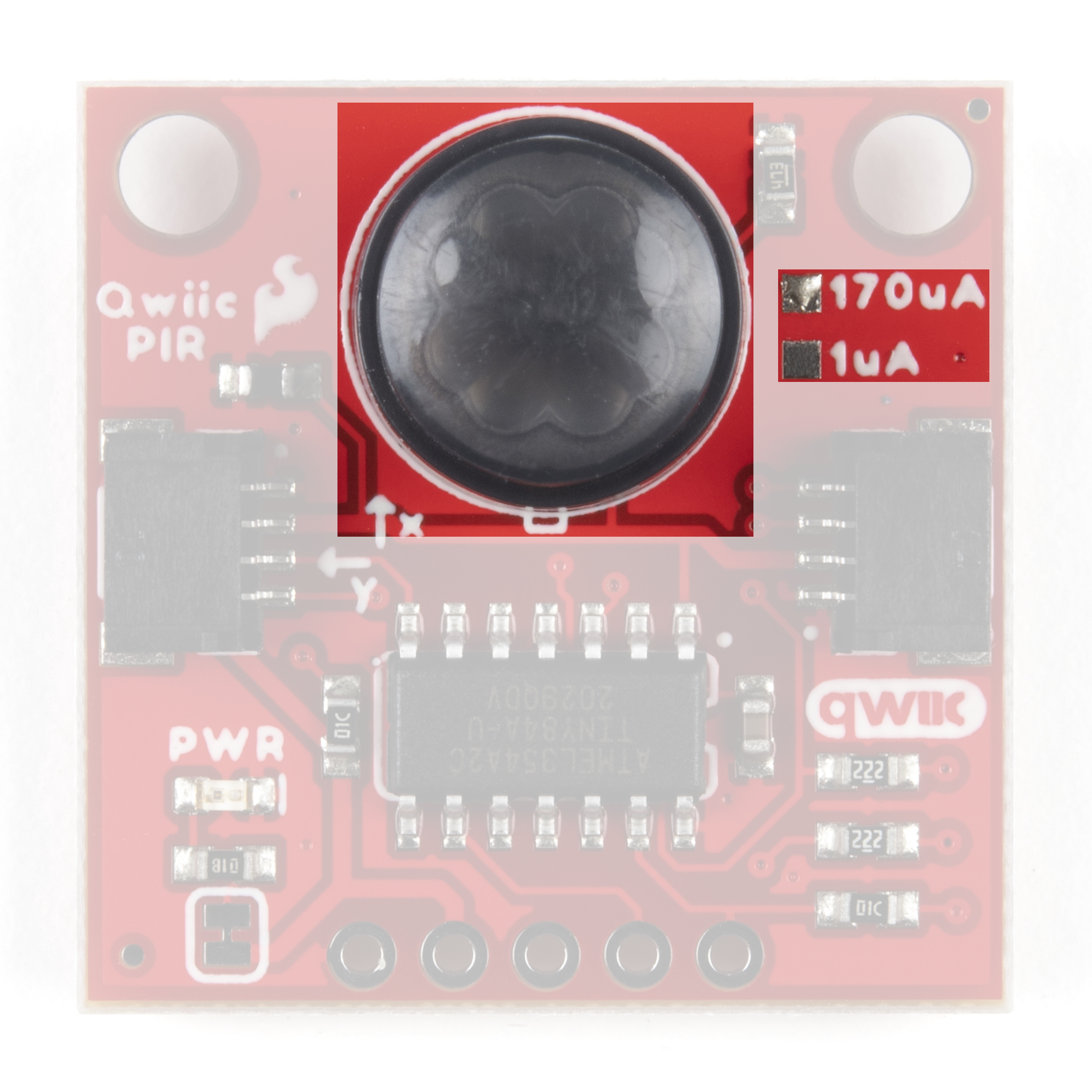
Input voltage (normally 3.3V) for the Qwiic PIR is provided either via the Qwiic connectors or through the 3.3V pin on the PTH header. The Output (OUT) pin is connected to a digital pin on the ATTiny84. Take note that both versions of the Qwiic PIR share the same PCB design and the version (1µA or 170µA) are marked by the solder pads "East" of the PIR sensor.
The two PIR sensors have very similar electrical and sensing characteristics with a few specific differences users will want to take note of prior to deciding which sensor best suits their needs. The tables below outline the Electrical and Detection Performance Characteristics to give users a basic overview. For a more detailed look at these two sensors, take a look at their respective specification sheets (EKMC4607112K & EKMB1107112) along with the Panasonic PIR Sensors - Product Brief (EKM-Series sensors are covered on page 8).
| Electrical Characteristics | |||||||
|---|---|---|---|---|---|---|---|
| EKMC4607112K | EKMB1107112 | ||||||
| Characteristic | Units | Min | Typ. | Max | Min | Typ. | Max |
| Operating Voltage | VDC | 3.0 | - | 6.0 | 2.3 | - | 4.0 |
| Current Consumption (Sensor Only) |
µA | - | 170 | 300 | - | 1[1] | 3 |
| Output Current | µA | - | - | 100 | - | - | 100 |
| Output Voltage | VDC | VDD-0.5 | - | - | VDD-0.5 | - | - |
| Circuit Stability Time (when voltage is applied) |
secs | - | - | 30 | - | 25 | 210 |
As mentioned above, the sensing performances of the PIR Sensors are very similar with a few notable differences. Also take note that PIR sensor performance can vary depending on the environment it is monitoring.
| Detection Performance Characteristics | |||||
|---|---|---|---|---|---|
| EKMC4607112K | EKMB1107112 | Notes | |||
| Temperature Difference | Value | Temperature Difference | Value | Target Conditions | |
| Detection Range | 8°C (14.4°F) | up to 7m | 4°C (7.2°F) | up to 7m | 1. Movement speed: 1 m/s 2. Target concept is human body (Object size:Around700×250mm) |
| 4°C (7.2°F) | up to 5m | 2°C (3.6°F) | up to 5m | ||
ATTiny84 IC
The ATTiny84 on this board comes pre-programmed with firmware to act as an intermediary between the PIR sensor and the microcontroller via Qwiic/I2C. The firmware handles monitoring the raw sensor output to detect objects entering or leaving the sensing area, automatically debouncing the output, triggering an interrupt whenever motion is detected and even storing a queue of sensing events you can pull from and clear.
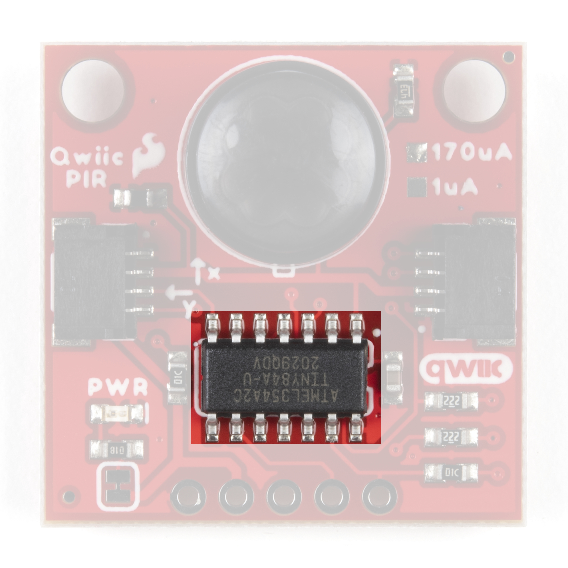
The default I2C address for the Qwiic PIR is 0x12 but can be switched to 0x13 by adjusting the ADR jumper. Alternatively, users can alter the address to a custom value using functions from the libraries or direct writes to the address register. Software setting of the I2C address is covered in more detail in the Arduino and Python library sections.
Finally, a 2x3 header broken out on the back of the board allows for programming the ATTiny84. This is primarily used for programming during manufacturing but can be used re-program the IC with custom firmware. You can download and modify the firmware from the Hardware GitHub Repository.
Qwiic/I2C Interface and Interrupt Pin
The easiest way to use the Qwiic PIR is with the Qwiic connect system. Connect it to your microcontroller or SBC with a Qwiic Cable to start communicating with it via I2C. For users who prefer a soldered connection, the I2C pins for the Qwiic PIR are broken out to a standard 0.1"-spaced PTH header.
 |
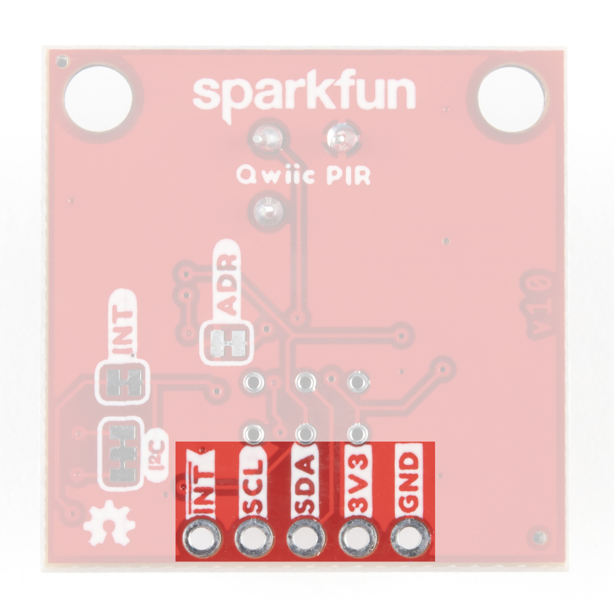 |
We've also included a dedicated Interrupt pin users can connect to an interrupt-capable pin on their microcontroller to trigger interrupt events based on the activity detected by the Qwiic PIR. Read on to the Arduino and Python sections for more information on how to configure and use this pin.
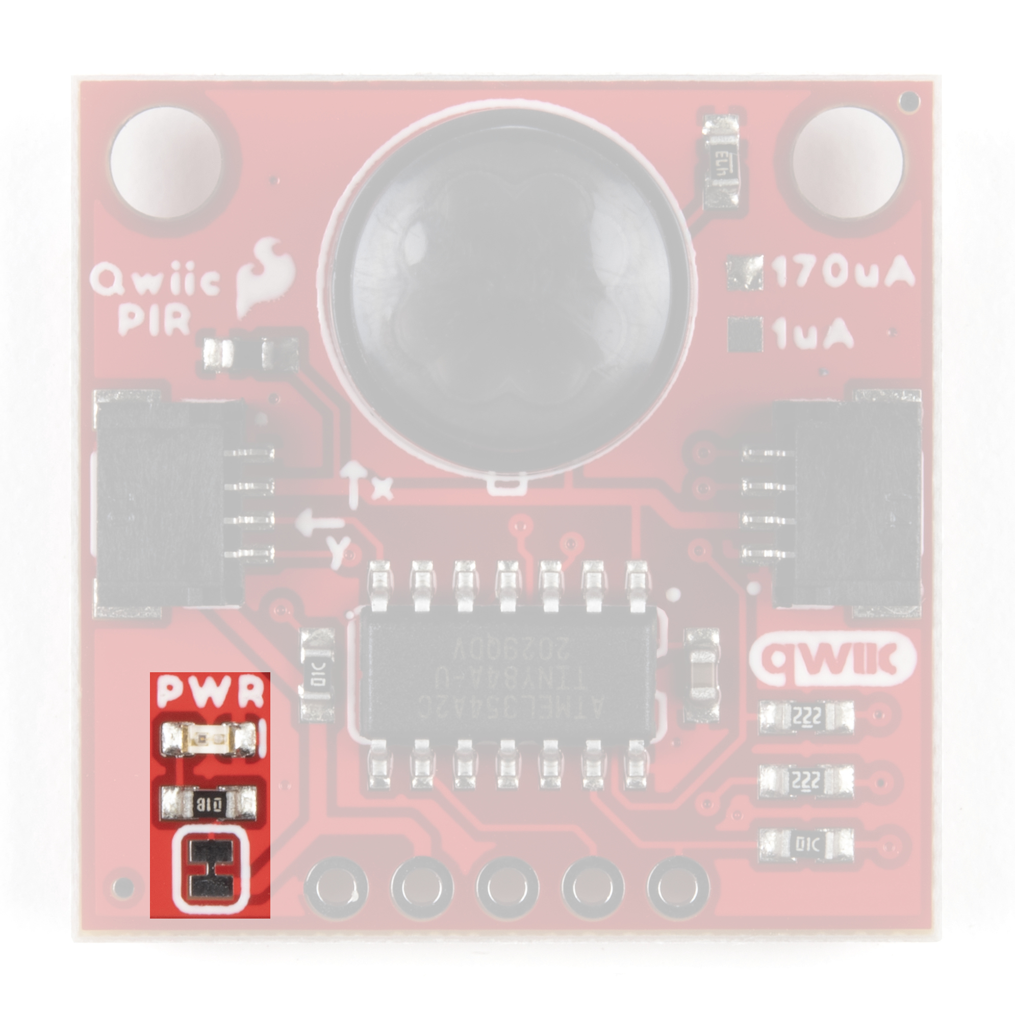
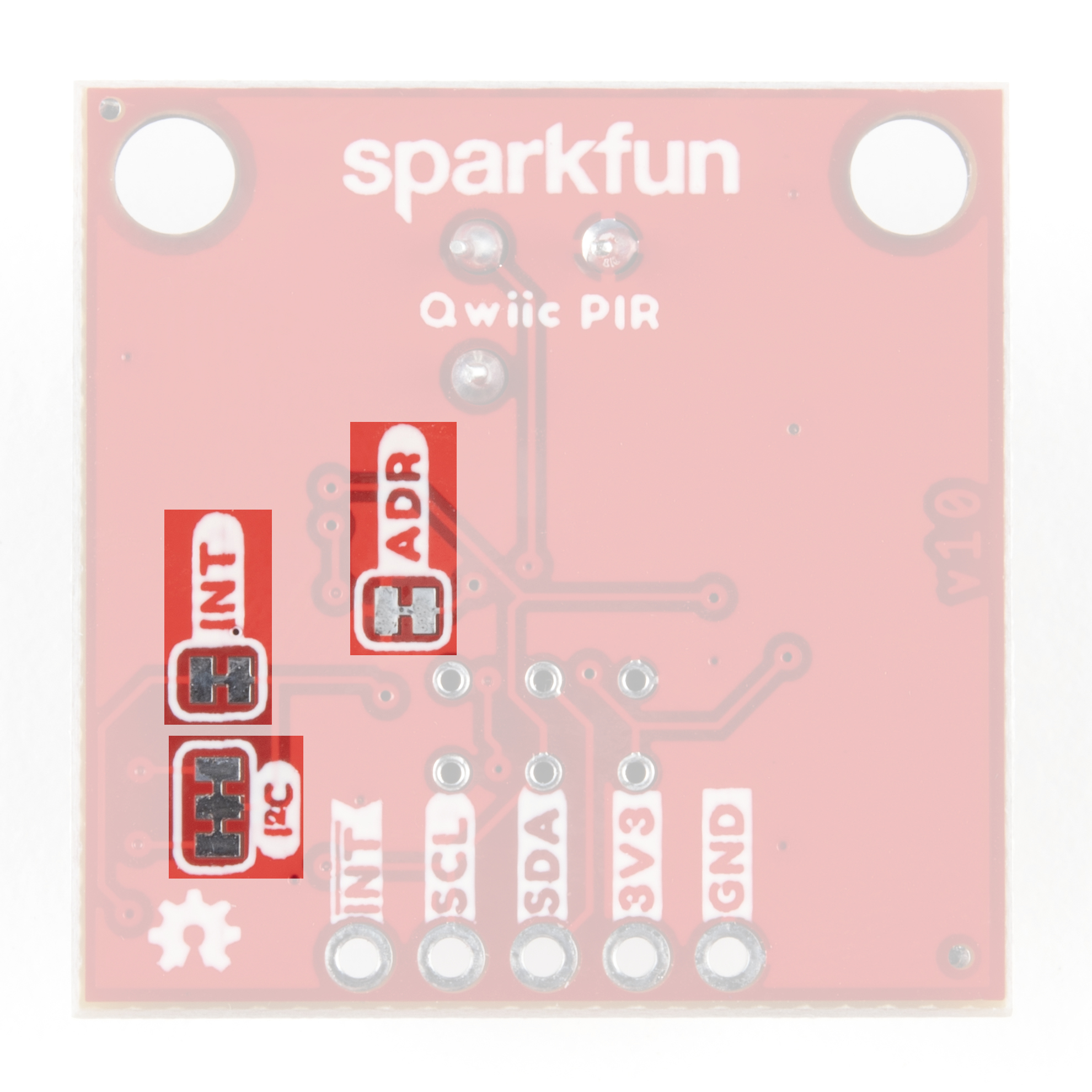
Solder Jumpers
There are four solder jumpers on the Qwiic PIR boards labeled PWR, I2C, INT and ADR. Let's briefly cover each jumper's functionality and default state.
|
|
Power Jumper
The Power (PWR) Jumper controls the power LED on the board and is closed by default. It ties the anode of the Power LED to 3.3V via a 1KΩ resistor. Open the jumper and disable the LED by severing the trace between the two pads. Disabling the Power LED helps to reduce the total current draw of the Qwiic PIR.
I2C Jumper
The I2C Jumper pulls the ATTiny84's SDA and SCL lines to 3.3V via a pair of 2.2kΩ resistors. The default state is closed. Open the jumper by severing the trace connecting the three pads to disable the pull-up resistors.
Interrupt Jumper
The Interrupt (INT) Jumper pulls the ATTiny84's Interrupt pin to 3.3V via a 10kΩ resistor. The default state of the Interrupt jumper is closed. The Interrupt Pin on the ATTiny84 is configured as an active LOW interrupt and must be pulled to logic HIGH (3.3V) to function properly. Disable the Interrupt pin by opening the jumper.
Address Jumper
The Address (ADR) Jumper sets the I2C address of the ATTiny84. The jumper is closed by default. Open the jumper by severing the trace between the two pads to change the I2C address from its default value (0x12) to 0x13.
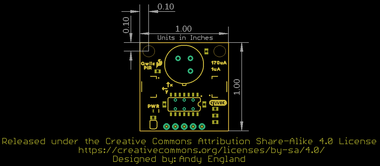
Board Dimensions
The Qwiic PIR matches the standard 1" x 1" (24.5mm x 24.5mm) form-factor for most Qwiic breakouts and has two mounting holes that fit a 4-40 screw.