Qwiic PIR Hookup Guide
 El Duderino,
  Englandsaurus
Hardware Assembly
With the Qwiic system, assembling your SparkFun Qwiic PIR incredibly easy. We'll cover the basics of hardware assembly here along with a couple of tips for using the Interrupt pin.
Connecting Qwiic Cables
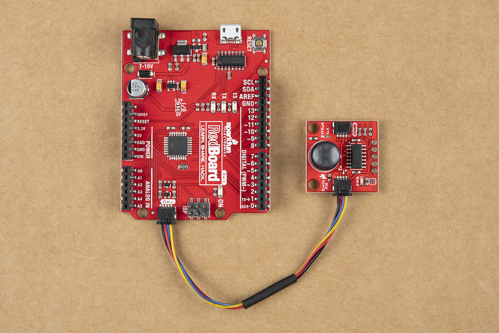
Assuming you are using a Qwiic-enabled development board like the RedBoard Qwiic shown below or you have a Qwiic shield or Qwiic adapter attached to your development board or Raspberry Pi/SBC, all you need to do to connect the Qwiic PIR to your circuit is to plug one end of your Qwiic cable into the Qwiic PIR and the other end into the Qwiic connector on your development board/shield.
Alternatively, you can use one of our adapter cables (male and female) to convert the Qwiic system to a standard jumper wire assembly. If you use one of these adapter cables, make sure you match the signals correctly:
- Black = GND
- Red = 3.3V
- Blue = SDA
- Yellow = SCL
If you prefer to not use the Qwiic connectors you can solder wire or header pins to the PTH header to make your connections.
Connecting Everything Up
If you do not plan to use the Interrupt pin on the Qwiic PIR go ahead and connect your development board to your computer via USB or if you are using a Raspberry Pi or other SBC, power it up.
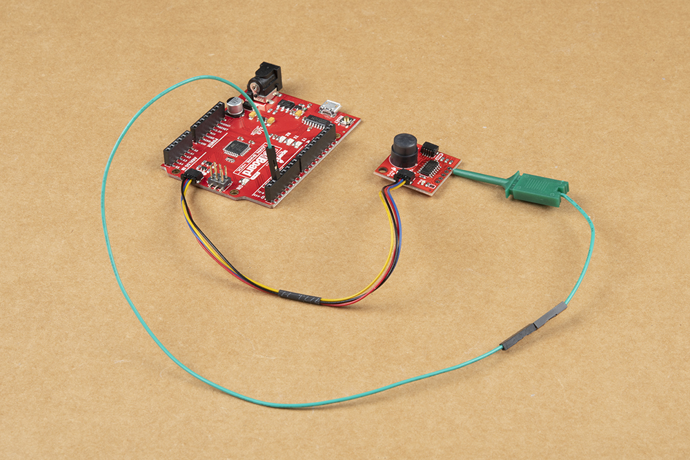
If you want to use the Interrupt pin, a bit more assembly is required. In order to use the Interrupt pin we need to either solder to it or, for quick prototyping, you can connect it to your development board/SBC using IC hooks like these that terminate in a standard male jumper wire connection.
After you have made your connection to the Qwiic PIR's Interrupt Pin, run that wire to a digital pin available for external interrupts. If you are not sure which pins are interrupt-capable, refer to your board's documentation for clarification. Since we're using the RedBoard Qwiic we can set up D2 or D3 as an interrupt pin. In the circuit below and the Interrupt Example in the Arduino library, the Interrupt pin is connected to D2:
Now that the Qwiic PIR circuit is fully assembled, connect the RedBoard to your PC via USB (or if using a Raspberry Pi or other SBC, power it on) and we can move on to uploading code and monitoring motion.