Qwiic Magnetometer (MLX90393) Hookup Guide
Introduction
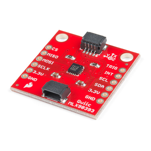
The MLX90393 is a tri-axial magnetic sensor capable of sensing very small fields while behaving as one would want and expect during saturation in larger fields (like a nearby magnet). It turns out the favorite HMC5883L and other such sensors that are intended for compass applications have a low dynamic range but also strange and undefined behavior in large fields. Ted Yapo did an incredibly extensive characterization of the sensor over on Hackaday. He published his controlled experiments testing a few sensors and found the MLX90393 to be superior.
The MLX90393 can be used as a compass sensor but also works well as a non-contact controller (joystick), flow meter (with magnetic impeller), or a linear actuator position sensor. The breakout board is also a part of SparkFun's Qwiic system, so you won't have to do any soldering to figure out what the magnetic fields look like.
In this hookup guide, we'll get going by getting some basic readings from the sensor, then look at how to configure the sensor on different I2C addresses.
Required Materials
To get started, you'll need a microcontroller to control everything in your project.
Particle Photon (Headers)
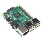
WRL-13774Raspberry Pi 3
DEV-13825Now, to get your microcontroller into the Qwiic ecosystem, the key will be one of the following Qwiic shields to match your preference of microcontroller:
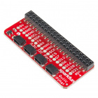
SparkFun Qwiic Shield for Photon
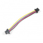
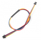
DEV-14477You will also need a Qwiic cable to connect the shield to your magnetometer, choose a length that suits your needs.
Qwiic Cable - 100mm
PRT-14427Qwiic Cable - 50mm
PRT-14426Qwiic Cable - 200mm
PRT-14428Qwiic Cable - 500mm
PRT-14429Or, here's the wishlist to follow along exactly with this guide:
Suggested Reading
If you aren't familiar with the Qwiic system, we recommend reading here for an overview.
 |
| Qwiic Connect System |
We would also recommend taking a look at the hookup guide for the Qwiic Shield if you haven't already. Brushing up on your skills in I2C is also recommended, as all Qwiic sensors are I2C.
I2C
Serial Terminal Basics
Qwiic Shield for Arduino & Photon Hookup Guide
Hardware Overview
Let's look over a few characteristics of the MLX90393 so we know a bit more about how it behaves.
| Characteristic | Range |
|---|---|
| Operating Voltage | 2.2V - 3.6V |
| Operating Temperature | -20°C - 85°C |
| Resolution | 128 Hz - 3.3 kHz |
| Current Consumption | 100 µA (Typ.) |
| I2C Address | 0xC0 |
Pins
The characteristics of the available pins on the magnetometer are outlined in the table below.
| Pin Label | Pin Function | Input/Output | Notes |
|---|---|---|---|
| 3.3V | Power Supply | Input | Should be between 2.2V - 3.6V |
| GND | Ground | Input | 0V/common voltage. |
| SDA | I2C Data Signal | Bi-directional | Bi-directional data line. Voltage should not exceed power supply (e.g. 3.3V). |
| SCL/SCLK | I2C Clock Signal | Input | Master-controlled clock signal. Voltage should not exceed power supply (e.g. 3.3V). |
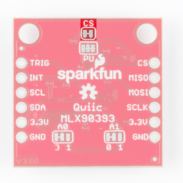
| CS | Chip Select | Input | Chip Select pin, digital input. Tied high for I2C operation, cut trace jumper and tie low for SPI. |
| INT | Interrupt | Output | Interrupt pin, active high, digital output. Also configurable as a data ready pin |
| TRIG | Reset | Input/Output | Trigger pin, active high, digital output. Also configurable as interrupt pin. |
Optional Features
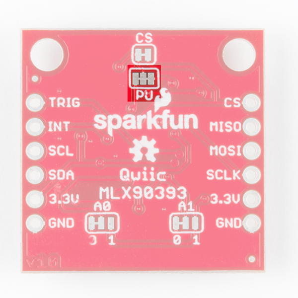
The Qwiic MLX90393 has onboard I2C pull up resistors; if multiple sensors are connected to the bus with the pull-up resistors enabled, the parallel equivalent resistance will create too strong of a pull-up for the bus to operate correctly. As a general rule of thumb, disable all but one pair of pull-up resistors if multiple devices are connected to the bus. If you need to disconnect the pull up resistors they can be removed by cutting the traces on the corresponding jumpers highlighted below.
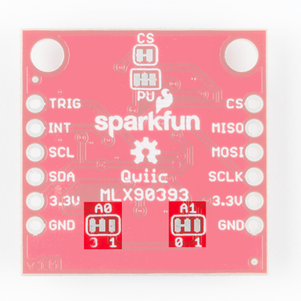
The I2C address of the Qwiic Magnetometer can be changed using the A0 and A1 jumpers on the back of the board. Simply cut the traces connecting each pad to ground (0) and solder the other side to connect it to 3.3V (1).
To operate the Qwiic Magnetometer in SPI mode, cut the chip select trace jumper (labeled below) and ensure that the CS pin is then connected to ground.
Hardware Assembly
If you haven't yet assembled your Qwiic Shield, now would be the time to head on over to that tutorial.
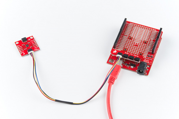
With the shield assembled, SparkFun's new Qwiic environment means that connecting the sensor could not be easier. Just plug one end of the Qwiic cable into the Magnetometer breakout, the other into the Qwiic Shield of your choice and you'll be ready to upload a sketch and figure out what the magnetic fields look like. It seems like it's too easy to use, but that's why we made it that way!
Example Code
Before we get into programming our Magnetometer, we'll need to download and install the magnetometer library. Ted Yapo has written a library to control the Qwiic Magnetometer. You can obtain the .zip for this library using the below button. Never installed a library before? That's ok! Checkout our tutorial on installing Arduino Libraries.
Note: This example assumes you are using the latest version of the Arduino IDE on your desktop. If this is your first time using Arduino, please review our tutorial on installing the Arduino IDE. If you have not previously installed an Arduino library, please check out our installation guide.
Since this isn't a SparkFun library, the example sketches are not included, so you'll have to download those separately from the GitHub page by clicking the below button. The example sketches are located in software
Go ahead and unzip these examples to a location of your choosing and open Example 1 - Basic Readings.
Example 1 - Basic Readings
Once we have our first example opened up, let's look at how things are structured as we set up our sensor. First we create our sensor, and then an array of floats to contain our data.
language:c
MLX90393 mlx;
MLX90393::txyz data; //Create a structure, called data, of four floats (t, x, y, and z)
Then in our setup loop, we must initialize our sensor, notice the delay afterwards, this gives the sensor time to initialize before we start attempting to talk to it.
language:c
mlx.begin(); //Assumes I2C jumpers are GND. No DRDY pin used.
delay(1000); //Allow the sensor to initialize.
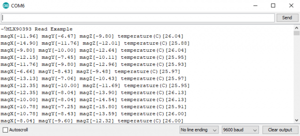
Once the sensor is initialized, our void loop() will read the data from our sensor into data, the array of floats we created earlier, and print it over serial to our serial monitor. Opening up your serial monitor to a baud rate of 9600 should display output similar to that shown below. The numbers are in units of µT.
Example 2 - Configure Sensor
Go ahead and open Example 2 from the location you saved it in. The only differences between this example and the previous one are in the setup() function. Notice how we now call the begin() function with 3 arguments, which are the value of the A0 jumper, the value of the A1 jumper, and the pin that we've connected to INT. The below code assumes that the A0 jumper has been cut from ground and soldered to 3.3V and that A3 is connected to the INT pin (sometimes referred to in the datasheet as the DRDY or data ready pin).
language:c
byte status = mlx.begin(1, 0, A3);
If we must change the address of our magnetometer due to overlapping addresses, ensure that the values we pass into begin() match up with the values of our address jumpers. The MLX90393 also has a ton of different ways to change the sensor behavior. You can set the gain, resolution of the x, y and z channels, oversampling rates, and even offsets of your x, y, and z channels. In this example however, we set the gain to 1 and the resolution of our x, y, and z channels to their finest setting, 0.
language:c
mlx.setGainSel(1);
mlx.setResolution(0, 0, 0);
A table showing the different possible resolutions of the sensor for the X and Y axes is shown below. These can be selected using the setGainSel(uint8_t gain) and setResolution(uint8_t x, uint8_t y, uint8_t z) functions. All resolutions are in units of µT/LSB.
XY Axis:
| Gain | Res = 0 | Res = 1 | Res = 2 | Res = 3 |
|---|---|---|---|---|
| 0 | 0.805 | 1.610 | 3.220 | 6.440 |
| 1 | 0.644 | 1.288 | 2.576 | 5.152 |
| 2 | 0.483 | 0.966 | 1.932 | 3.864 |
| 3 | 0.403 | 0.805 | 1.610 | 3.220 |
| 4 | 0.322 | 0.644 | 1.288 | 2.576 |
| 5 | 0.268 | 0.537 | 1.073 | 2.147 |
| 6 | 0.215 | 0.429 | 0.859 | 1.717 |
| 7 | 0.161 | 0.322 | 0.644 | 1.288 |
Shown below is the table containing the possible combinations for resolutions on the Z axis. Once again, units are in µT/LSB
Z Axis:
| Gain | Res = 0 | Res = 1 | Res = 2 | Res = 3 |
|---|---|---|---|---|
| 0 | 1.468 | 2.936 | 5.872 | 11.744 |
| 1 | 1.174 | 2.349 | 4.698 | 9.395 |
| 2 | 0.881 | 1.762 | 3.523 | 7.046 |
| 3 | 0.734 | 1.468 | 2.936 | 5.872 |
| 4 | 0.587 | 1.174 | 2.349 | 4.698 |
| 5 | 0.489 | 0.979 | 1.957 | 3.915 |
| 6 | 0.391 | 0.783 | 1.566 | 3.132 |
| 7 | 0.294 | 0.587 | 1.174 | 2.349 |
Since we are simply connecting our magnetometer on a different address, our output should be similar to the one in the first example.
Resources and Going Further
For more information, check out the resources below:
- MLX90393 Schematic (PDF) - Schematic for the MLX90393.
- MLX90393 Eagle Files (ZIP) - Board design files for the MLX90393.
- MLX90393 Datasheet (PDF) - Datasheet for MLX90393 Magnetometer.
- Qwiic System Landing Page
- GitHub Repos
- SparkFun Showcase: Qwiic MLX90393 Triple Axis Magnetometer
Need some inspiration for your next project? Check out some of these related tutorials:
SparkFun Qwiic Digital Temperature Sensor - TMP102 Hookup Guide
SparkFun Air Quality Sensor - SGP30 (Qwiic) Hookup Guide
SparkFun Qwiic Alphanumeric Display Hookup Guide
Qwiic ToF Imager - VL53L5CX Hookup Guide
Or check out this blog post about using a magnetometer as a compass:
