Qwiic Distance Sensor (VL53L1X) Hookup Guide
This Tutorial is Retired!
This tutorial covers concepts or technologies that are no longer current. It's still here for you to read and enjoy, but may not be as useful as our newest tutorials.
View the updated tutorial: Qwiic Distance Sensor (VL53L1X, VL53L4CD) Hookup Guide
Hardware Overview
First let's check out some of the characteristics of the VL53L1X sensor we're dealing with, so we know what to expect out of the board.
| Characteristic | Range |
|---|---|
| Operating Voltage | 2.6V-3.5V |
| Power Consumption | 20 mW @10Hz |
| Measurement Range | ~40mm to 4,000mm |
| Resolution | +/-1mm |
| Light Source | Class 1 940nm VCSEL |
| I2C Address | 0x29 |
| Field of View | 15° - 27° |
| Max Read Rate | 50Hz |
Pins
The following table lists all of the VL53L1X's pins and their functionality.
| Pin | Description | Direction |
|---|---|---|
| GND | Ground | In |
| 3.3V | Power | In |
| SDA | Data | In |
| SCL | Clock | In |
| INT | Interrupt, goes low when data is ready. | Out |
| SHUT | Shutdown, can be pulled low to put the IC in shutdown mode. | In |
Optional Features
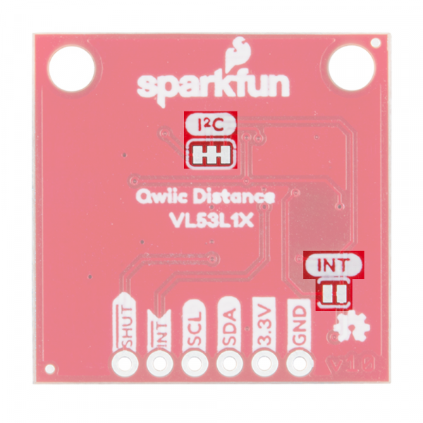
The VL53L1X breakout has pull up resistors attached to the I2C bus as well as the interrupt pin; if multiple sensors are connected to the bus with the pull-up resistors enabled, the parallel equivalent resistance will create too strong of a pull-up for the bus to operate correctly. As a general rule of thumb, disable all but one pair of pull-up resistors if multiple devices are connected to the bus. If you need to disconnect the pull up resistors they can be removed by cutting the traces on the corresponding jumpers highlighted below.
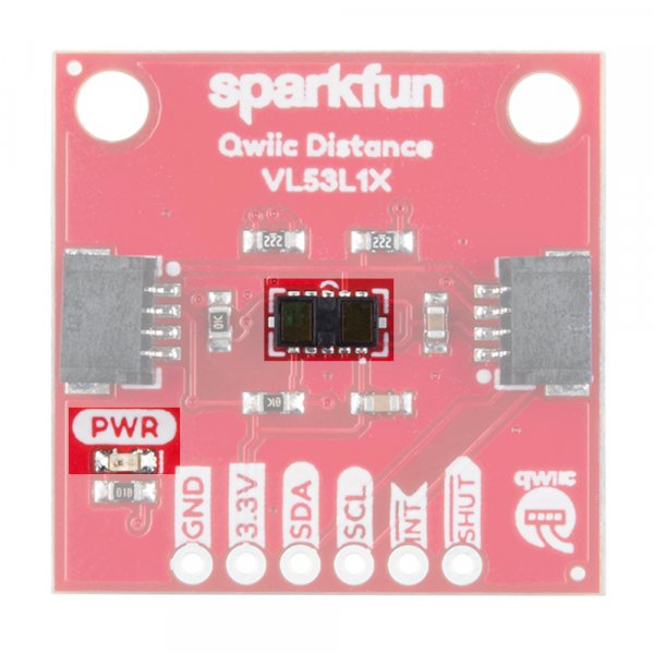
The onboard LED (highlighted below) will light up when the board is powered, and the sensor (also highlighted below) should be left uncovered in your application.

