Prototype Wearable LED Dance Harness
 bboyho
Understanding Your Circuit
The circuit for the wearable LED harness is simple. Let's take a look at the left side of the harness that holds the battery, adapters, and LEDs.
Initial Circuit
Power is connected to the "+12V" pad of the non-addressable LED strip. To complete the circuit and power the LEDs, ground is connected to each color's pad labeled "G," "R", or "B." Green and blue were chosen to make cyan from the primary colors. For one side of the harness, LED segment A consisted of a long strip of 33x LEDs. LED segment B and C consisted of 3x LEDs each.
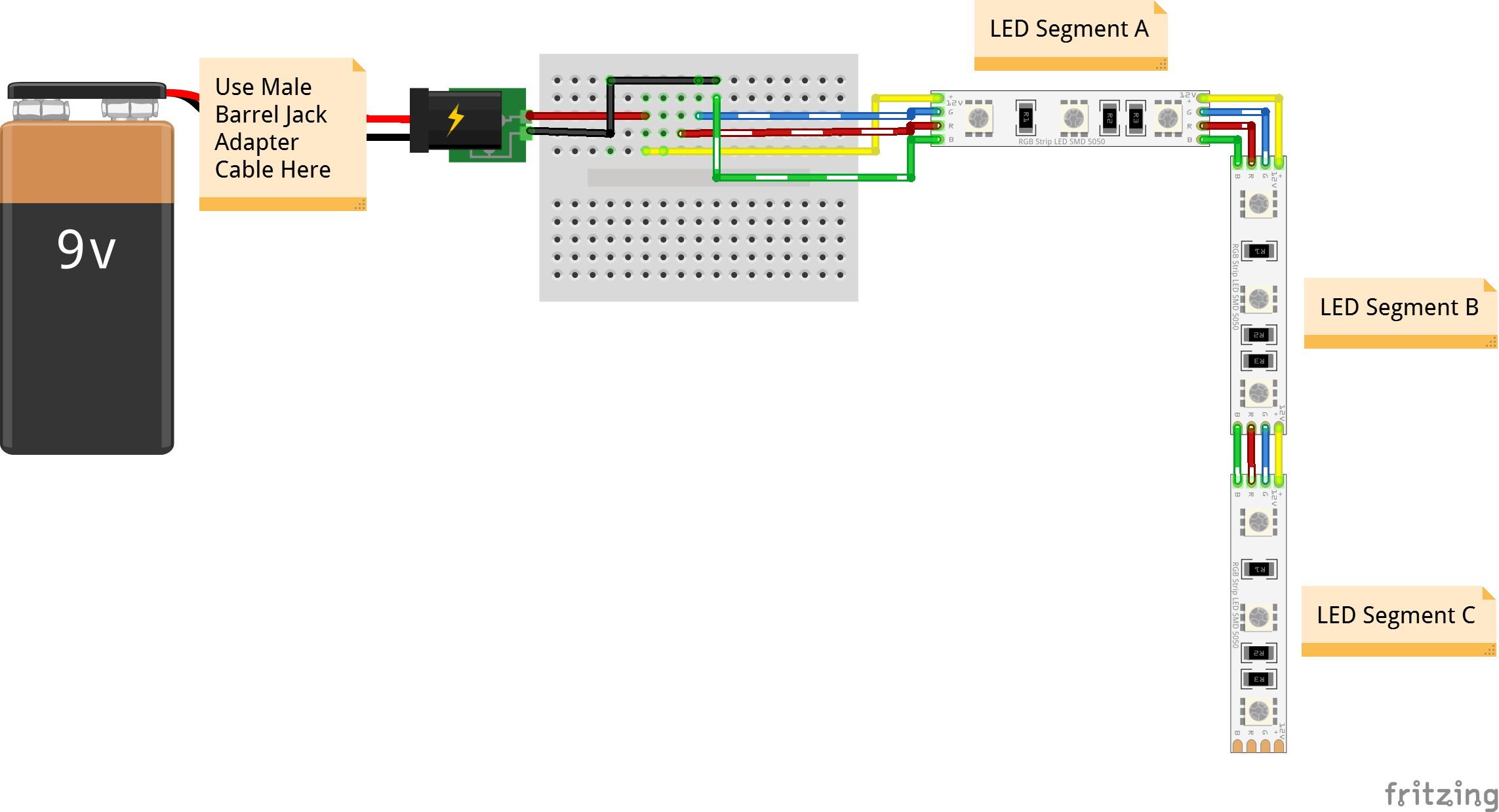
A 9V battery and custom made adapters were used for each harness. Keep in mind that a 9V battery is not able to power all three colors simultaneously. However, using two colors was sufficient enough for the project and performance.
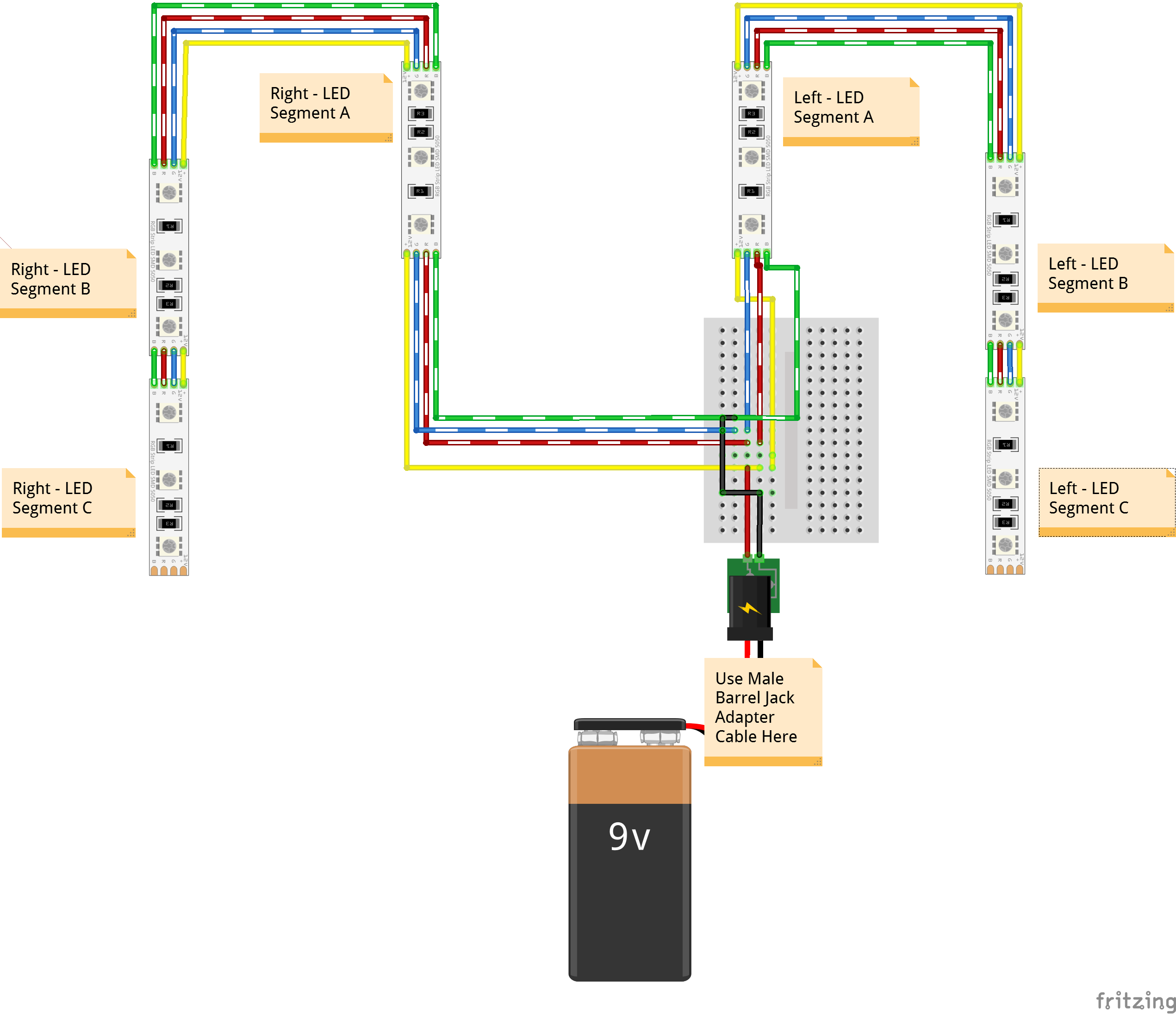
Complete Circuit
The connection was then wired in parallel on the other side of the harness by connecting to the same rails on the solderable breadboard.