Prototype Wearable LED Dance Harness
 bboyho
Hardware Hookup
Connecting LED Strip Segments
Cut the LED strip at the center of the exposed pads using a diagonal cutter. The dot and dashed line in the image below is where you will need to perform the cut. Make sure to remove part of the silicone tube in order to be able to access the LED Strip's pads.

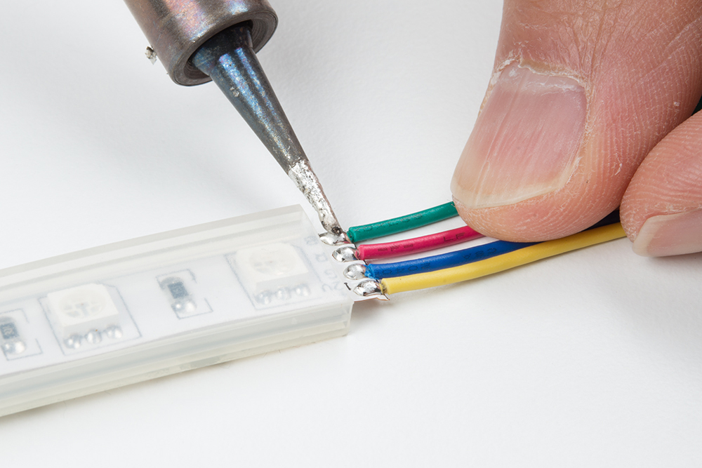
Cut half of the 12" premium jumper wires and strip the insulation. Then solder the wires to each of the LED strip's pads.
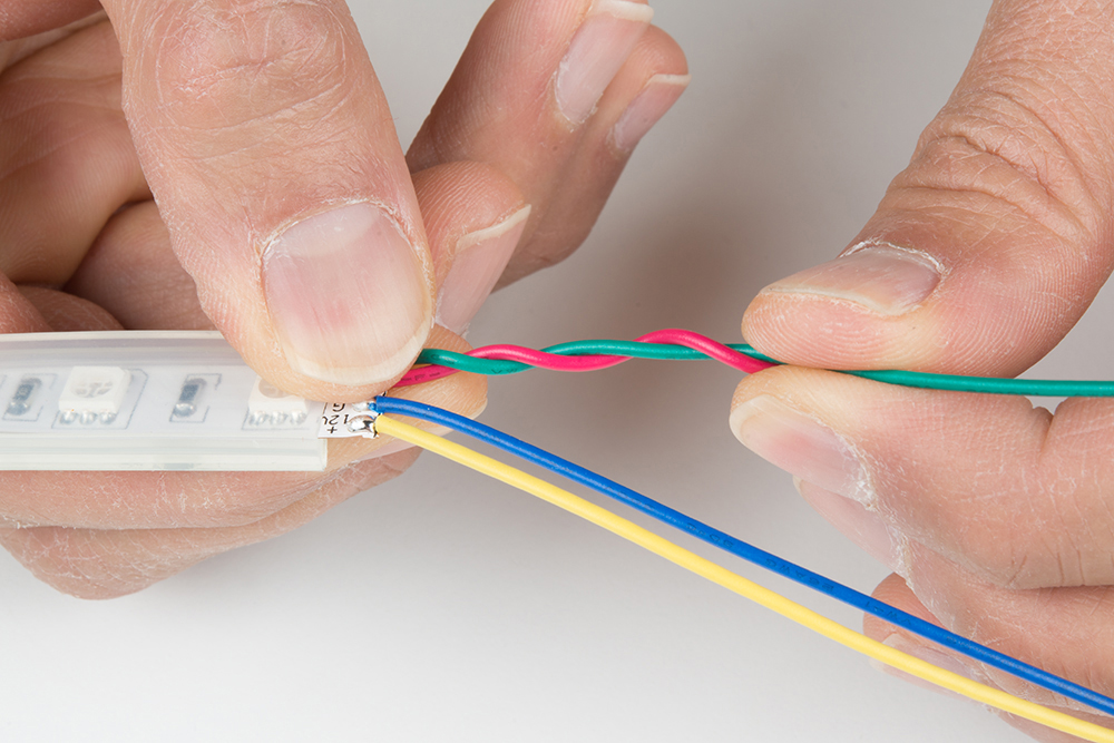
The connection to the pads needed to be secure so I decided to braid the wires together to manage the connections. I was inspired by McCall’s tutorial when completing projects. To braid your wires, twist a pair of wires in a counterclockwise pattern between your index finger and thumb using both hands. I decided to start with the green and red wires.
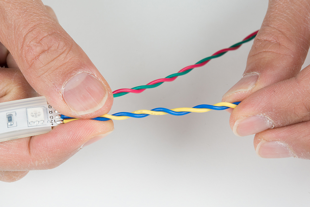
Twist the other pair of wires in a counterclockwise pattern.
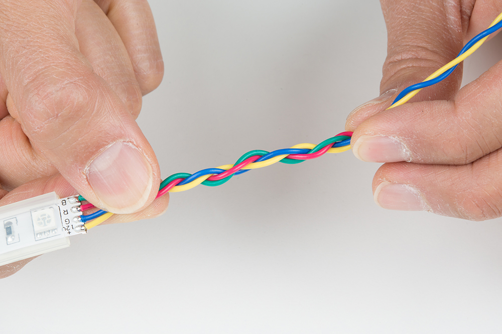
Twist the pairs of wires in a clockwise pattern.
Repeat for segment B and C. The segments will be using shorter wire.
|
|
|
Clean Solder Joints
If you were using water soluble flux, clean the solder joints with de-ionized water and a toothbrush. Dry the LED strips thoroughly using compressed air. Luckily, SparkFun has a PCB cleaning room. As an alternative, you could use water from the sink and towels.

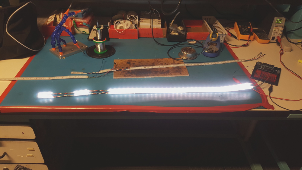
Test LED Strips
Once dry, test the LED strips to make the colors matched and the wires are connected to its respective pads. I decided to use a benchtop power supply set to output about 9V to verify the connection.
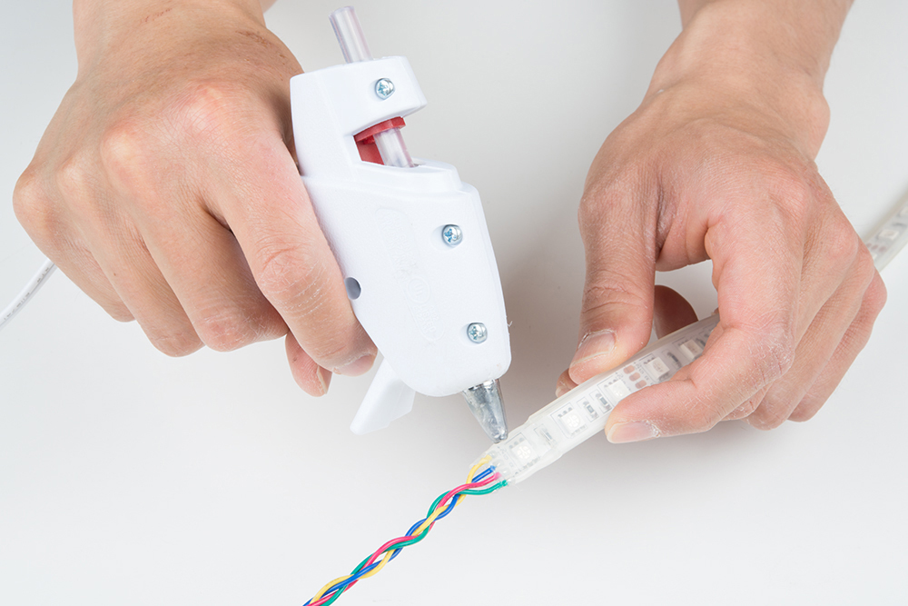
Secure w/ Hot Glue
Add hot glue to the terminals to secure the wires further.
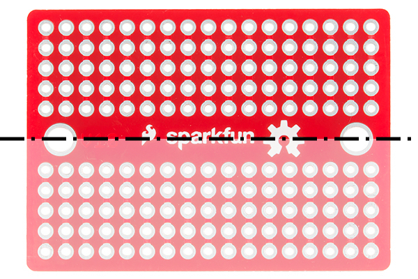
Custom Power Adapter w/ Solderable Breadboard
Using a dremel and Panavise, carefully cut the solderable breadboard in half.
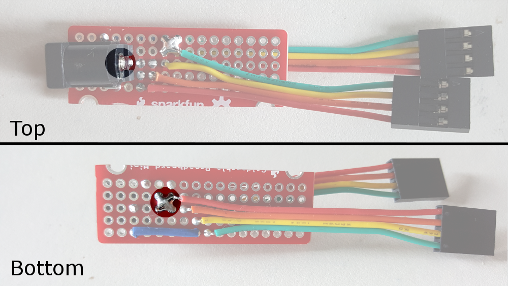
Solder the female barrel jack connector to the board so that the connector is flush with the edge.

Cut the 1x4 pin jumper wire in half and strip each wire using 0.1" spacing. Solder the wires as illustrated earlier in the Fritzing diagram.
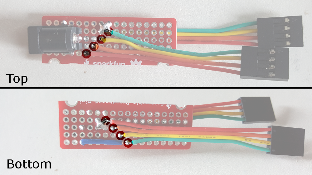
Solder the GND pins together for two of the colors with a solder bridge. Then connect it back to the barrel jack connector an extra wire to the sheath.
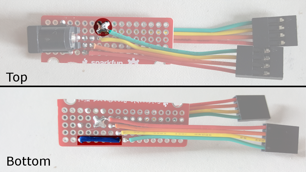
Solder the center pin to the "+12V" pin.
Clean, dry, and test the board with a multimeter, power supply, and the LED strips. Feel free to label the connections with a marker or paint.
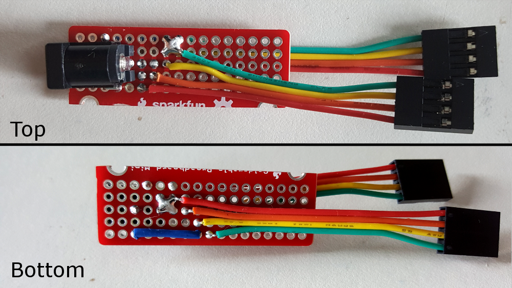
Finally, secure the wires and insulate the connection using hot glue just like the LED strip.