Proto Pedal Example: Programmable Digital Pedal
 Byron J.
The Circuit
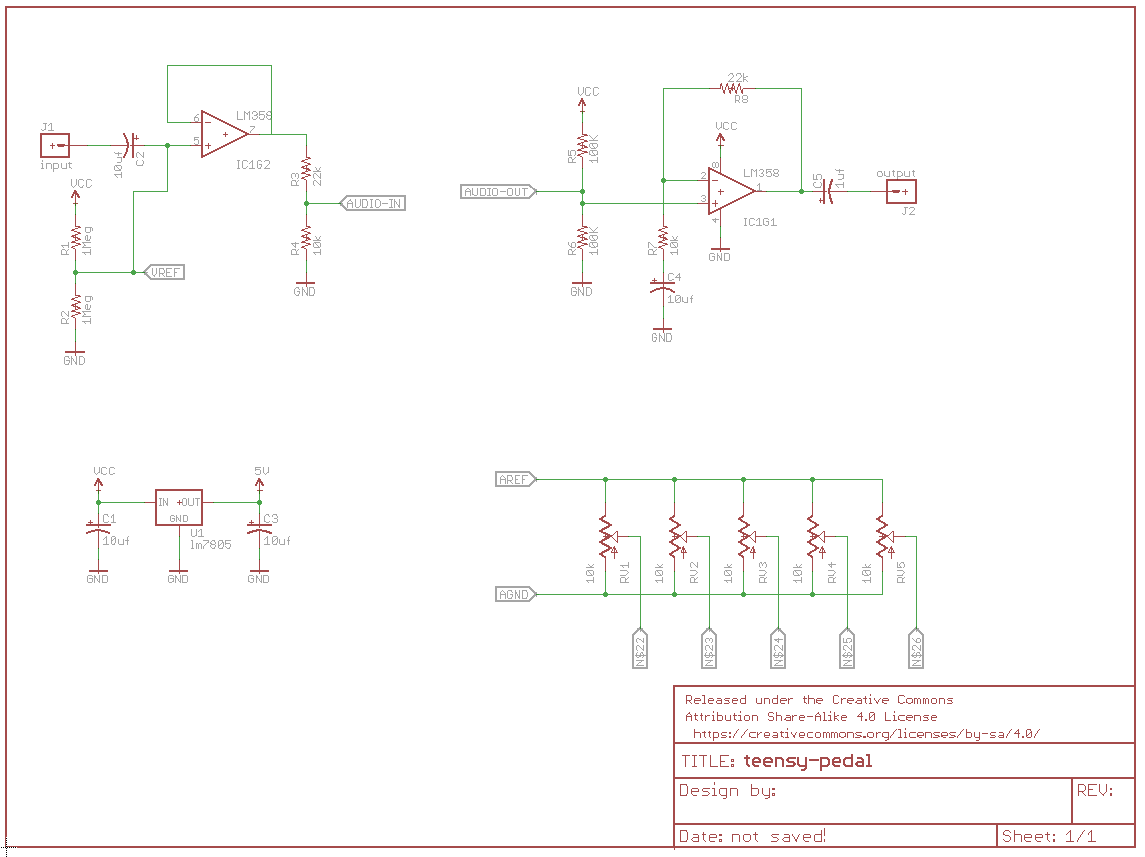
The most important component is in the middle of the schematic: the Teensy and audio adapter. We're using a simplified symbol to represent them, which only shows the connections we're using.
Theory Of Operations
We're going to quickly describe what each section of the circuit does.
Input Buffer
The first portion of the circuit is the input buffer.
It consists of one stage of an LM358 operational amplifier, configured as a voltage follower. It's input is biased to 4.5 VDC with the pair of 1M Ω resistors, and the input signal is coupled to them via the 10 uf cap. The output of the buffer matches the input signal -- the buffer increases the input impedance, but doesn't amplify or attenuate the signal.
It provides a reasonably high impedance of 500K Ω, defined by the parallel 1M resistors. 1M Ω is the highest value resistor in the SparkFun Resistor Kit -- if you've got higher value resistors (such as 2.2 M Ω), they should provide even better performance.
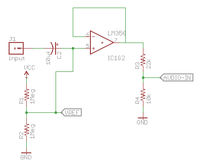
The output of the buffer amplifier feeds the divider of R3 and R4, which attenuates the signal by 10K/(10K + 22K), or 10/32, roughly one-third the input value.
Since this amp stage is powered directly from the 9 VDC supply, it has roughly 9 Vpeak-to-peak overall headroom. Dividing the output by 1/3 constrains it to about 3 Vpp, which more closely matches the input headroom of the Teensy line input that it feeds.
Output Amplifier
The output of the Teensy also has about 3 Vpp headroom, which we amplify back to the 9 Vpp range using an amplifier with a gain of 3.
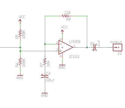
The gain of this noninverting stage is determined by the equation 1 + (Rfeedback/Rshunt), or 32/10, the reciprocal of the attenuation of the input amplifier. This pair of circuits achieve what's known as unity gain, the combined result being a multiply by one. What goes in comes back out the same.
Voltage Regulator
The Proto Pedal operates in a world of 9 V batteries and wall adapters, while the Teensy can operate from a miximum of 6 VDC. To help bridge the gap, we're using a simple LM7805 linear voltage regulator.
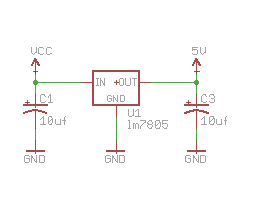
It turns the 9 V into 5 V. The Teensy draws about 60 mA, and the regulator is dropping the voltage by 4 V, so this regulator has to dissipate about 1/4 Watt as heat. It gets a little warmer than room temperature, but doesn't get appreciably hot.
The Teensy has further onboard regulators, dropping the 5 V down to 3.3 V.
Analog controls
Finally, there are five potentiometers, wired as voltage dividers between Teensy 3.3V and AGND.
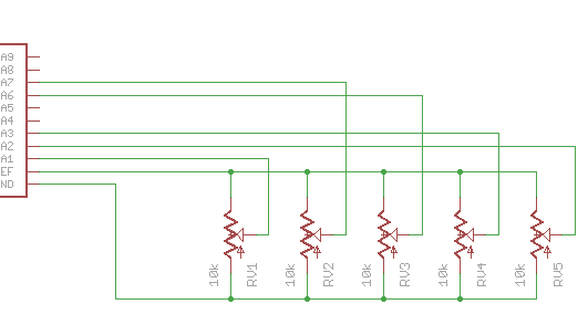
The wipers of these pots are connected to Teensy ADC inputs A1, A2, A3, A6, and A7. These controls can be assigned to effect parameters in firmware, and are not hardwired to specific parameters.