Proto Pedal Example: Programmable Digital Pedal
 Byron J.
Assembly Part 2 (Teensy and controls)
Teensy Section
The next portion of the circuit that we'll be building is the Teensy and Audio Adapter. We'll start by turning them into a subassembly, then putting it on the pedal PCB.
Optional Modification
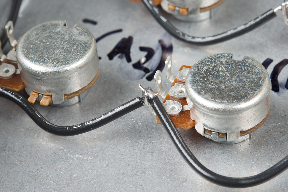
As wen mentioned earlier, the Teensy Audio adapter has a rather high noise floor. On the PJRC forums, user omjanger has posted a modification that helps reduce the noise slightly. It involves putting a 1 MΩ resistor in parallel with the 0.15 uf capacitor on the VAG pin of the codec chip. This modification is shown below.
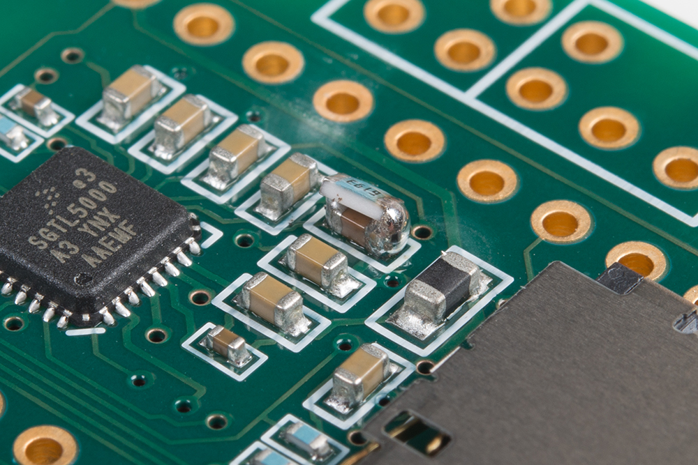
If you chose to undertake this modificaton, be warned: it takes an extremely careful touch to get the resistor in place without removing the capacitor entirely, or bridging adjacent components with solder blobs.
Prepare the Stack
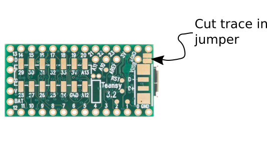
Since we're going to be powereing the Teensy from the regulator on the pedal circuit board, we want to cut the jumper that bridges the USB bus voltage to the Teensy power input. We used a hobby knife to cut the trace, and a continuity checker to make sure the cut was complete.
Next we want to stack the teensy and audio adapter with header pins.
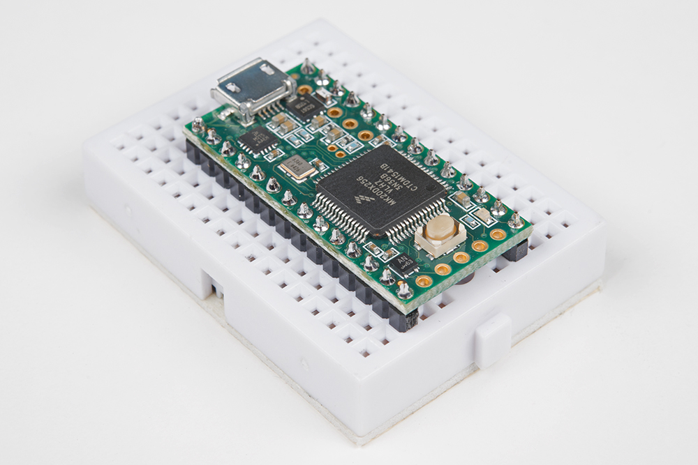
The first step is to break off two 14-pin sections of snappable header, and solder them to the Teensy, with the longer portion of the pins pointing downwards. Below, we're using a small breadboard to hold the pins straight while we solder.
Then we remove the Teensy from the breadboard, and put the pins through the audio adapter. Double check the alignment before proceeding: the USB port on the Teensy and the headphone plug on the audio board both face the same direction.
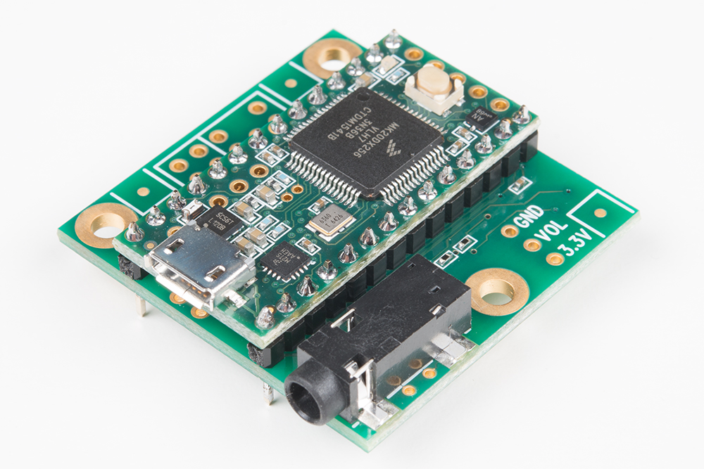
The audio board gets soldered to the pins from below.
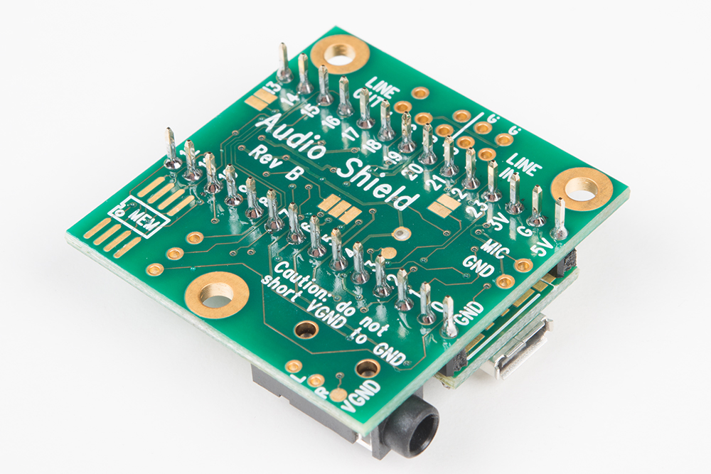
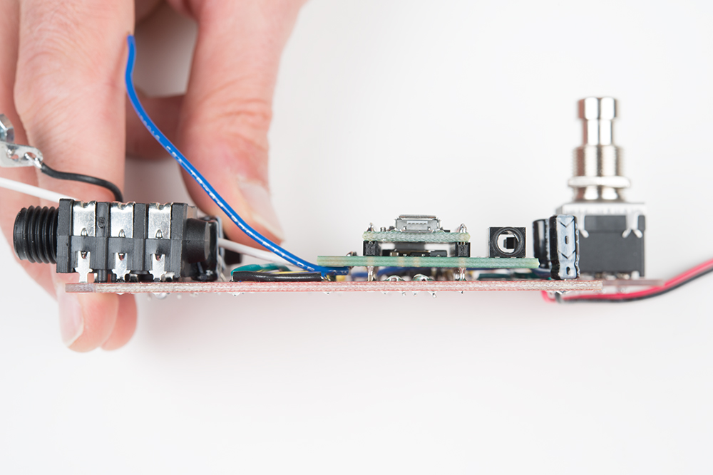
While we're looking at the bottom of the board, let's solder two more wires to the audio adapter. Here, you can see white and blue wires connected to the left line input and the left line output. Each wire is about 4 inches long -- we'll trim them to length later.
| Wire Color | Connection | Length |
|---|---|---|
| White | Line out L | 4 inches |
| Blue | Line In L | 4 inches |
They're inserted from the bottom of the board...
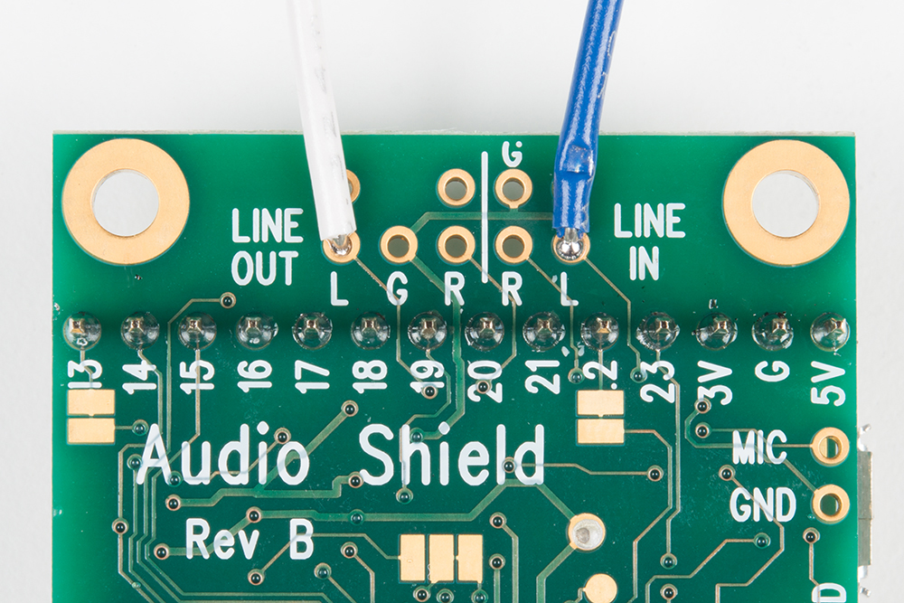
...and soldered to the top of the board.
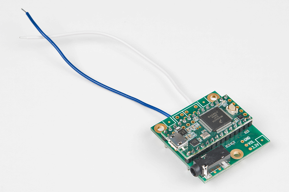
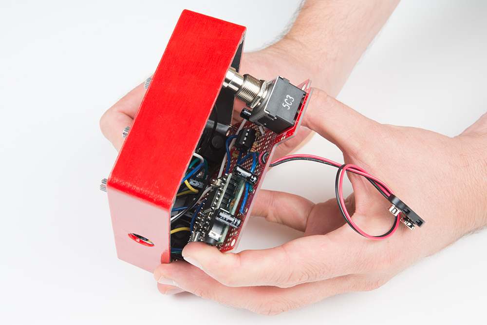
Now we put the stack on the proto pedal circuit board.

The stack is placed with the USB and headphone jacks pointing to the left, where the USB plug will align with the hole in the left side of the chassis. It spans from column 2 to column 15, and the pins were placed in rows C and G. We don't want to bottom of the audio adapter to accidentally touch anything on the pedal PCB, as we're using a coffee stirrer as a shim while we solder.
You can see the clearance between the stack and the pedal PCB below.
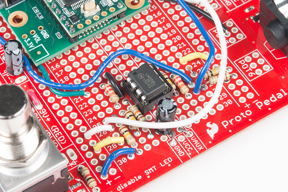
The last piece of this step is to run the wires from the line connections back to the analog section.
| Wire Color | Source | Destination |
|---|---|---|
| White | Line Out L | 25A |
| Blue | Line In L | 27I |
Before soldering, we ran the wires to their destination, and trimmed some excess, helping avoid clutter.
Incremental Test
Testing this step is similar to the previous incremental test. Connect the input, output and power. Then load the throughput sketch. This sketch allows the Teensy to pass audio from line input to line output.
Toggle the stomp switch a few times. The output of the pedal should be the same amplitude when it is engaged or bypassed. You will likely be able to hear the raised noise floor of the Teensy when the pedal is engaged.
Controls section
The final quadrant of the circuit is the panel controls. Like the previous step, we'll build a subassembly, then integrate it with the main circuit board.
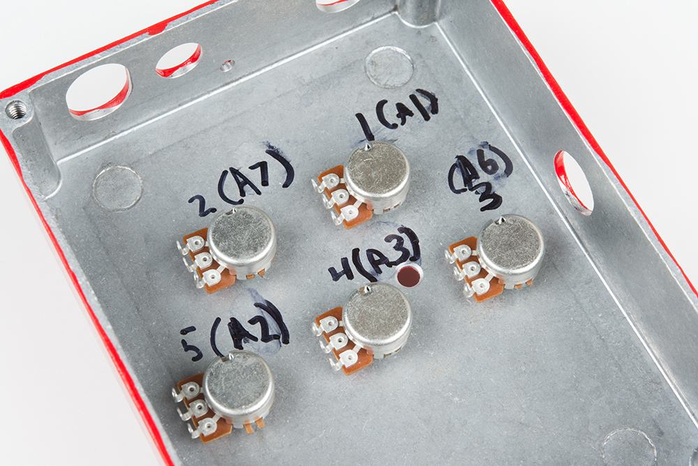
To start, mount the five 10K potentiometers in the chassis, and tighten them in place. Notice that we've numbered each pot (1 through 5), and labeled it with it's corresponding Teensy ADC input (A12, A7, A6, A3 and A2). The numbers run right-to-left beacuse we're looking from the inside of the box.
The pots are wired as parallel voltage dividers between the Teensy AGND and 3.3V signals. Since they're in parallel, they'll be wired as busses.

As indicated in the photo above, the left legs of the pots are daisy-chained with black wire, and the right legs are daisy-chained with blue wire. The middle terminal of each pot will get it's own color coded wire in a later step.
For the bus that runs from pot to pot, we used short pieces of solid core wire. Each leg in the daisy-chain has a wire to each of it's neighbors. We stripped the ends of each wire, then pushed them through the holes in the pot terminal.
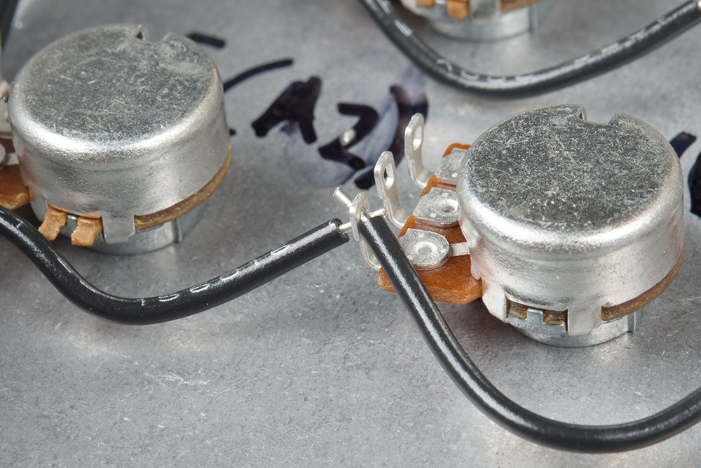
We then flow solder onto that nexus, making sure to avoid cold solder joints.
The black and blue daisy chains are run between pots, and then we add pigtails to run to the main PCB. Because these wires need to be flexible, we selected about 6 inches of stranded hookup wire, and soldered them to the end of the respective daisy chains.
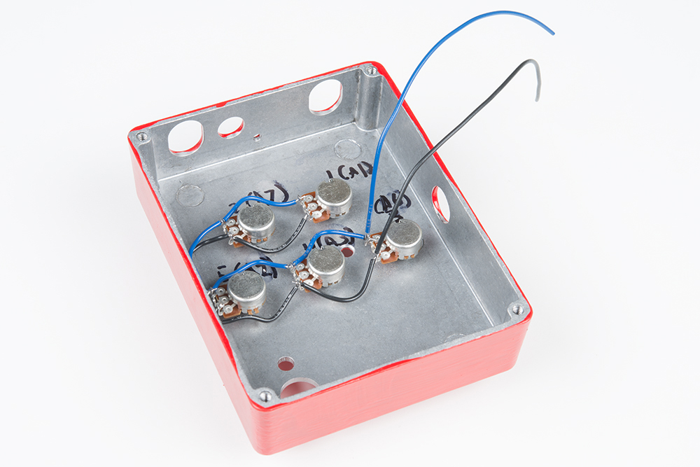
With the buses complete, we need to add five more wires to the potentiometer wipers. Again, we're using stranded hookup wire, each about 6 inches long.
The following table and photos illustrate the connections.
| Pot connection | Wire Color | Board Destination |
|---|---|---|
| Clockwise Bus | Blue | Pot1 Right |
| Counterclockwise Bus | Black | Pot1 Left |
| Wiper 1 | Green | Pot1 Middle |
| Wiper 2 | Yellow | Pot2 Middle |
| Wiper 3 | Blue | Pot3 Middle |
| Wiper 4 | White | Pot4 Middle |
| Wiper 5 | Black | Pot5 Middle |
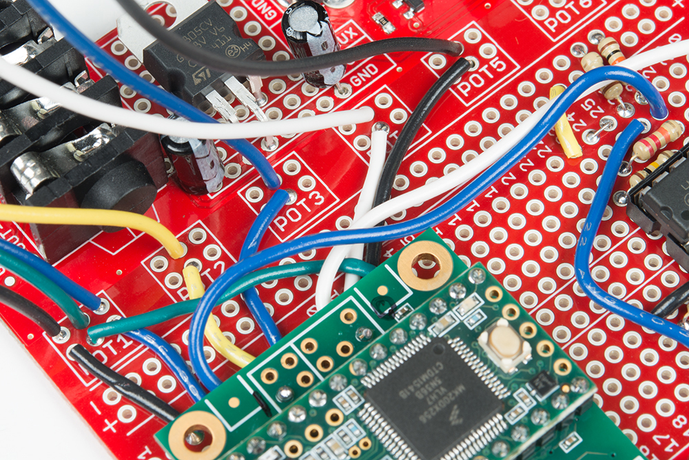
When these wires in place, you should have wires as seen below. Note that we've got two blue and two black wires -- the wiper signals (to the left of the photo), and the daisy chained buses (to the right of the photo). Be careful to keep them straight when you connect them to the PCB!

The black and blue bus wires connect to the left and right pads of the Pot1 area, respectively. The blue wiper wire connects to the center of pot 3, and the black wiper wire connects to the center of pot 5.
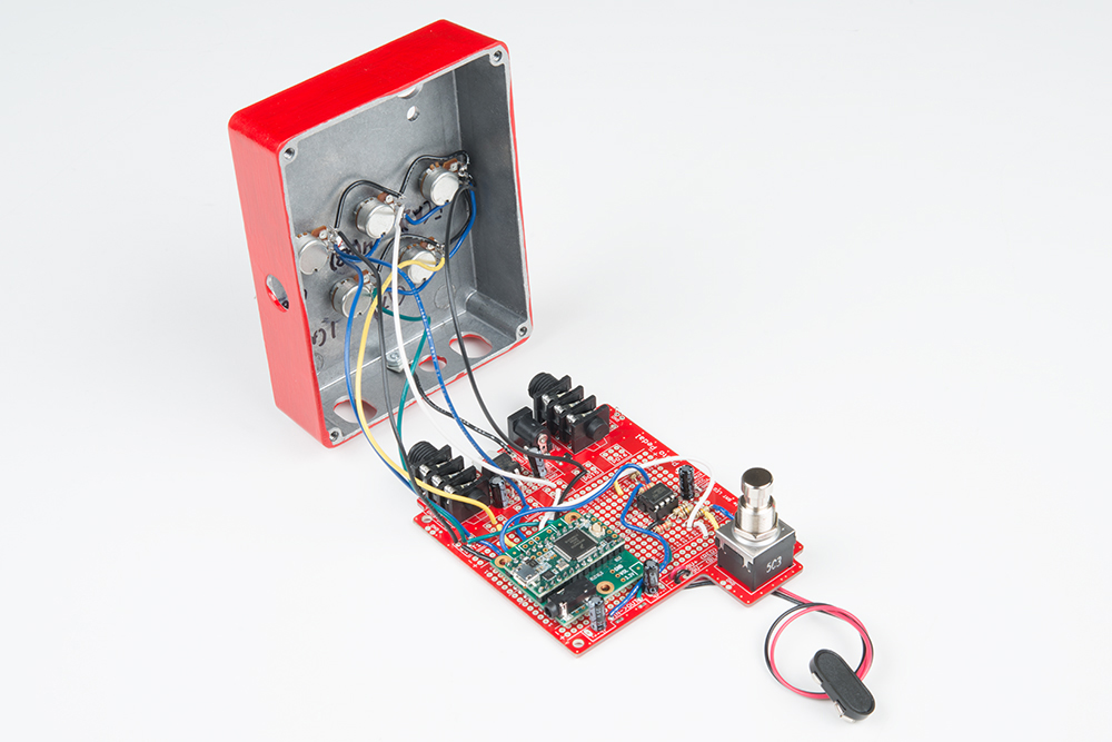
With the controls soldered to the PCB, you should have an overall assembly as depicted below.
Notice that we've also bolted the ground lug from the PCB to the chassis.
Final Incremental Test
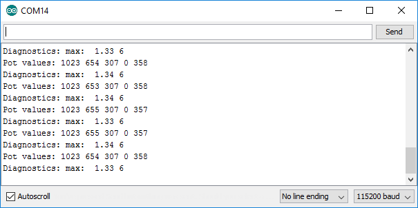
The throughput test sketch that we loaded in the last step also serves as an integration test for the panel controls. If you open the serial port, you notice that it periodically prints a set of five values, showing the potentiometer readings. As you turn each pot, the values should change from 0 when set counterclockwise, to 1023 at when fully clockwise.
Close It Up
When the tests are passing, we're done soldering, and we can close the pedal up.
To put the PCB into the chassis, angle it so the TRS jacks go through the oblong holes, then pivot the board so the switch goes through its hole. As it closes, make sure that the control wires aren't hanging up on anything, and if you've got a PTH LED, take care to get it through the chassis hole, too.
Then put the external hardware on to hold the board in place. The switch gets a hex nut, and each TRS jack has a plastic washer and hex nut.
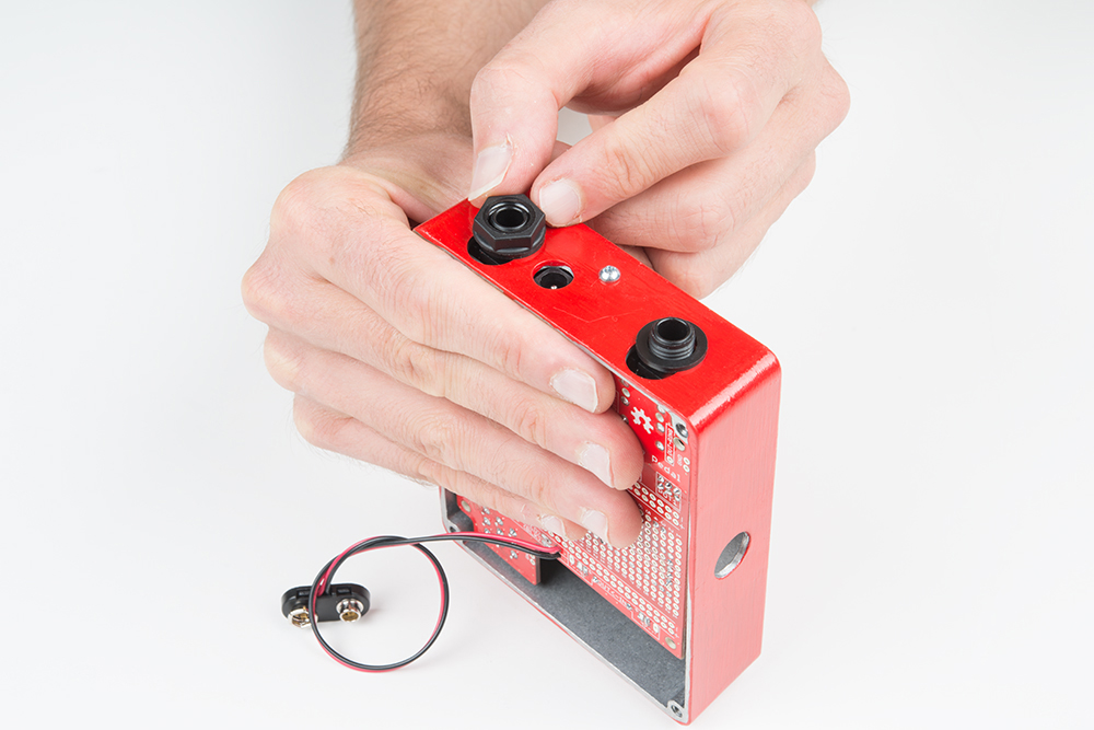
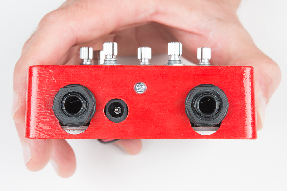
Before you tighten all of the hardware, doublecheck the aliignment of the barrel jack. It should be centered in the panel hole, as shown below. This alignment reduces the chances of the barrel jack shorting to the chassis, or the bottom of the PCB coming into contact with the lid of the enclosure.
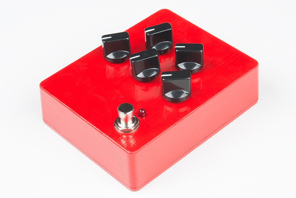
Finally, put the back on the box, and put knobs on the pots.