Proto Pedal Assembly and Theory Guide
 Byron J.
Theory Of Operations
Guitar pedals are their own specialized engineering discipline. A number of design conventions have evolved through the years that are now commmonplace. The Proto Pedal incorporates some of these conventions.
Bypass switching
The chunky footswitch on many pedals is a derivative of an old-fashioned automotive hi-beam switch.
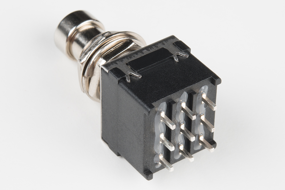
Inside the switch, there are actually three separate switches that actuate together when the button is pressed. This switch is actually designed specifically for guitar pedals.
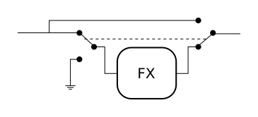
Through the years, a wide variety of bypass switching circuits have been used, many of which use a two-pole switch. The most usable configuration of a two pole switch uses both sections of the switch to steer the signal around the circuit in a "true bypass" configuration. When bypassed, the Proto Pedal passes signal even if the circuit isn't powered.

The protopedal uses a variant of true bypass switching. The input of the effect is tied to ground when the effect is bypassed, which keeps some high-gain circuits from misbehaving.
Indicator LED
In the discussion of bypass switching, we only used two of the three poles on the switch. The third section is used to switch the LED, showing the status of the pedal.
There are two options for LED indicators. By default, there is a surface mount red LED on the PCB, so you can tell the bypass status on your workbench. If you want to defeat this LED, remove the solder blob on SJ1.
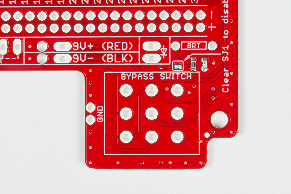
The second LED option allows for a through-hole 5mm LED near the footswitch, which aligns with the hole in the chassis. There is a through-hole bias resistor next door, marked BRT, so you can configure the brightness of the LED.
AC Coupling
Adding the Offset
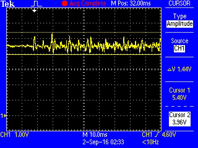
Guitar signals generally swing about 0V, with an amplitude of around one volt, peak-to-peak (though this varies quite a bit with different pickups, string materials, and playing styles).
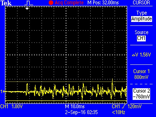
Pedal circuits are typically powered by a single 9V DC battery, which limits the signal swing to that range. The negative peaks of the signal fall below ground, which is outside the region where the circuits operate.
To aid this situation, an offset is added to the signal. This is called a "DC bias."
As you analyze pedal schematics, you'll learn to identify where this offset is generated. It's frequently a pair of equal-value resistors wired as a divider between 9V and ground, sometimes with a cap in parallel with the lower resistor. Let's look at an actual schematic and identify the offset voltage.

(Schematic courtesy Jack Orman, used with permission)
The offset voltage is produced by the divider formed by R8 and R9. The node where they meet will be one-half of V+ (4.5V if powered by a 9V battery).
In more complex schamatics, the half-rail voltage might be used multiple places in the circuit, and there might be more than one divider.
Coupling Capacitors
The DC bias voltage is required inside the circuit, but it needs to be prevented form reaching the outside world. If the DC bias finds its way to the bypass switch, it will cause pops or thumps when the switch is is actuated. Similarly, the guitar, amplifier, and other pedals are expecting the signal to be centered around 0 V. The bias is removed using capacitors on the effect input and output.
The the Super Buffer schematic above, the input coupling capacitor is C1 and the output coupling capacitor is the parallel combination of C2 and C3.
The Proto Pedal anticipates that circuits will need those caps, providing footprints for them on the edge near the battery.
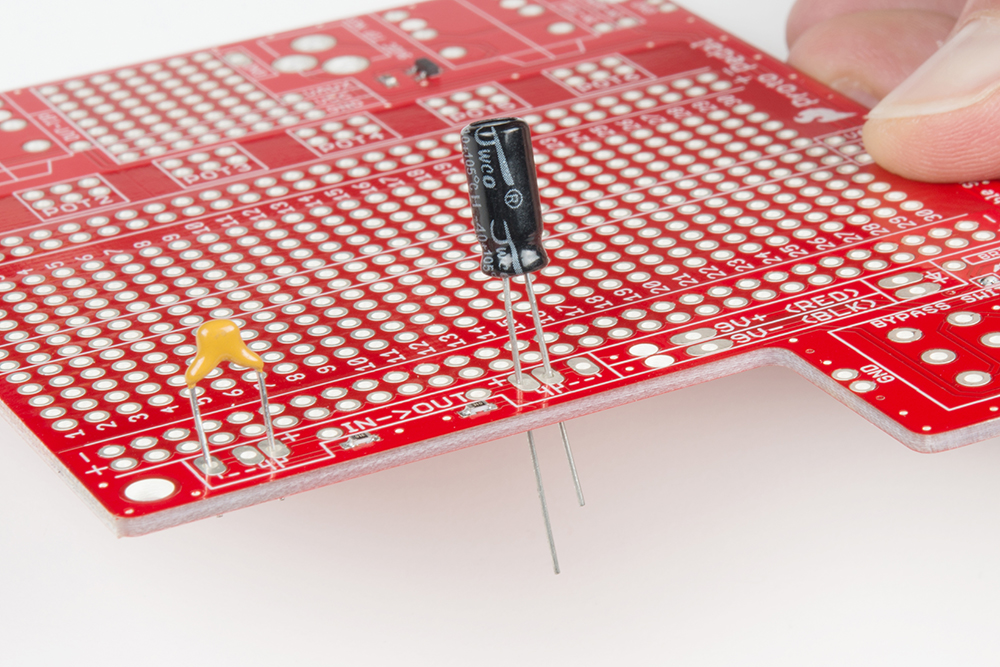
The Proto Pedal also has 1 MΩ pulldown resistors on the external sides of the coupling caps, similar to the 2.2M Ω R5 and R7 in the buffer schematic. Some types of capacitors leak the bias voltage, slowly charging the external sides of the caps. The pull-down resistors keep the external sides of the caps at ground potential, preventing popping when the switch is actuated.
Wait, There's No Power Switch?
In the discussion of the stomp switch above, you'll notice the switch is being used to steer the signal through the effect, and turn the LED on and off. It's not actually turning the circuit on and off.
If you're familiar with guitar peals, you understand that the input jack needs to be connected for the pedal to come on. The input jack functions as the power switch!
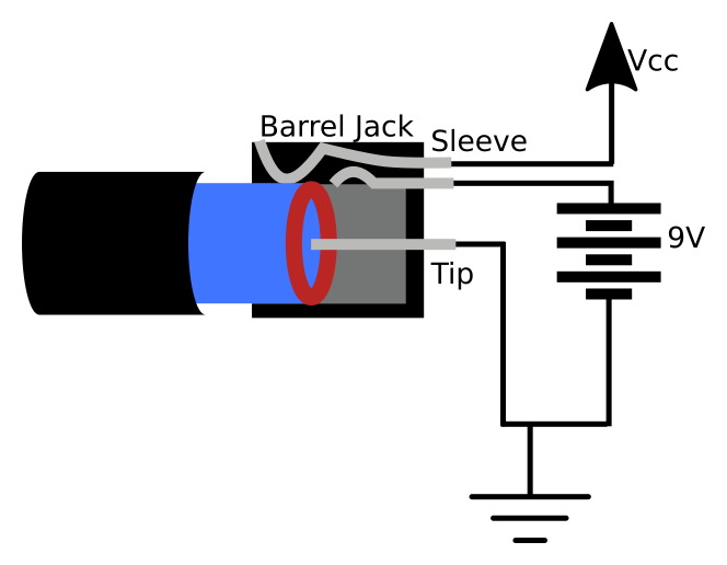
Let's take a closer look at how this works, by looking at the components in question.
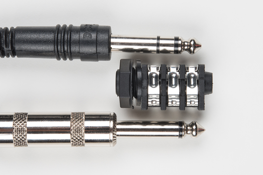
Here, from top to bottom, are
- A tip-ring-sleeve (TRS) 1/4" jack.
- A 1/4" TRS socket.
- A standard guitar cable with a tip-sleeve (TS) 1/4" jack.
The difference between the TS and TRS jacks is that the TRS jack has a third conductor (the ring) between the tip and sleeve. Or, seen from the opposite perspective, the TS jack is a TRS jack with the ring and sleeve shorted together.
The input on an effect pedal is actually a tip-ring-sleeve socket, with three conductors. When a TS cable is plugged into it, it bridges the ring to the sleeve. Pedals use that connection as a low-side power switch, connecting the negative terminal of the battery to the pedal ground.
If you've used pedals with 9V betteries, you quickly learned that you had to unplug them when you weren't using them if you didn't want the batteries to die.
Power Input Selection
The Proto Pedal has two power sources: the barrel jack and the 9 volt battery snap. These connections are arranged so that when the barrel is plugged in, the battery is out of the circuit.
This relies on a somewhat obscure detail in the construction of the barrel jack: it has an extra, spring loaded, contact.
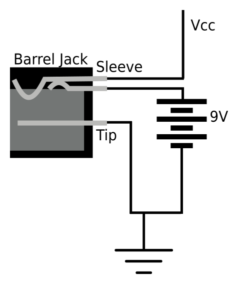
When nothing is plugged in, the spring holds the second and third contacts together. When the barrel is plugged in, the jack pushes the contacts apart, disconnecting the battery.
In the sophisticated world of pedalboard design, it's common that the battery is omitted entirely, and the pedals are powered by DC power supplies.
Finally, as we mentioned in the introduction, guitar pedals use a barrel jack polarity that's backwards from other disciplines. Just in case the wrong DC adapter finds its way into the picture, the power connections are protected using a P-channel MOSFET that will only conduct when forward biased. A reverse-polarity adapter (or fumbling a 9V battery against the snap) won't cause any damage - it simply won't work.
Some Notes on "Tone Suck"
Through the years, some guitar pedals have become notorious for introducing unwanted changes in the input signal. Perhaps they make the sound quieter, darker, the low end disappears, or just becomes somewhat indistinct -- sometimes even with the pedal bypassed!
Unlike some hard to prove audiophile concepts, "Tone Suck" is a real phenomena, which can be easily explained with a little engineering analysis.
An electric guitar pickup is a high impedance inductive source. If the load on that source is too high, it forms a frequency dependent voltage divider, and the high end disappears. Early in the pedal era, this fact wasn't fully recognized, and some circuits had unusually low input impedance.
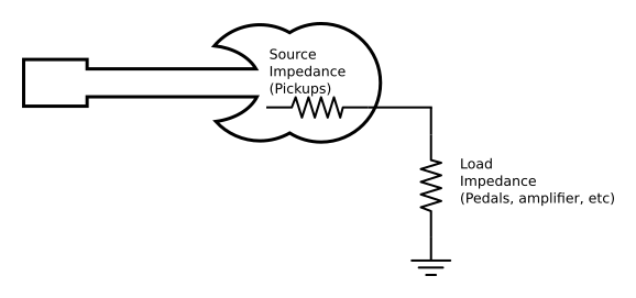
To prevent undue loading, the load impedance should be ten times the source impedance.
In round numbers, the source impedance of guitar pickups is commonly in the 10KΩ to 25KΩ range. To work well with both sources, a guitar input should have ten times that impedance, or 250K -- even higher, such as 1 MΩ, is better. Typical hi-fi and pro-audio inputs are in the 10KΩ to 47KΩ neighborhood. If a guitar is plugged directly into them, it probably loses some mojo.
There are two solutions to the impedance loading problem. The first is to design circuits with a suitably high input impedance. The second is to add a buffer stage in front of the low Z input. The buffer could be as simple as a JFET or MOSFET configured as a source follower, or even another pedal inserted between the guitar and the low impedance input.
The bypass circuitry in older pedals sometimes cut corners, as well. There have been switching strategies that use a single pole switch to simply select between the input signal or the effect output, so the effect is always loading the pickups, even when bypassed.

With a two pole stomp switch, the switch can steer the signal completely around the effect circuit, removing the load entirely.
Finally, the coupling capacitors in some pedals are simply too small, causing a loss of low end.
The Proto Pedal incorporates a number of features that should prevent these problems.
- The bypass switch is configured in a true-bypass configuration.
- The input impedance of the PCB is 1 MΩ -- high enough to not form an undue load on most guitars.
- The coupling capacitors on the input and output are user-selectable, so they can be chosen to prevent low-end loss.