Proto Pedal Assembly and Theory Guide
 Byron J.
Assembly Instructions
Parts
In the Proto Pedal box, you will find the following pieces.
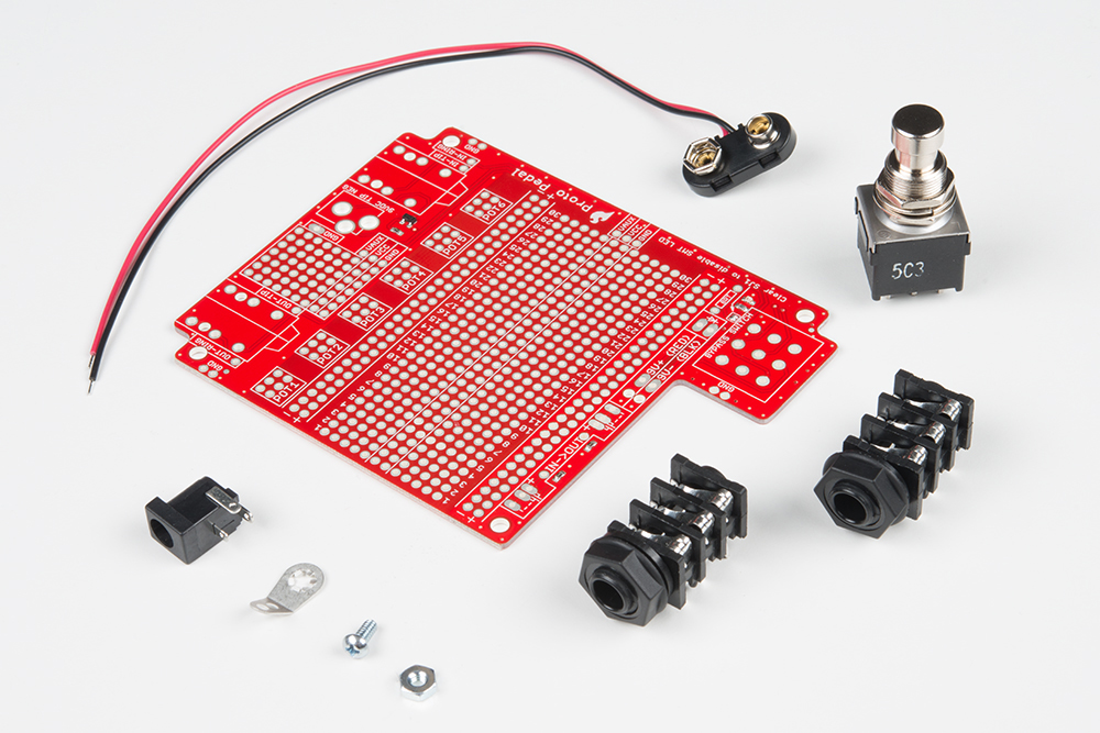
Clockwise from the top left, you see:
- One heavy-duty 9 Volt battery snap.
- One 3PDT stomp switch.
- Two TRS jacks.
- One each 4-40 nut, machine screw and star washer ground lug.
- One 2.1mm Barrel jack
- One PCB with SMT work completed
Additionally, we highly recommend the pre-drilled chassis. It's a standard sized cast aluminum box, which does double duty as an assembly jig, to help get the jacks and switch aligned correctly.
You'll also need a short piece of stranded hookup wire.
Tools
To assemble the Proto Pedal, we recommend the following tools and materials:
- Soldering Iron
- Lead-based or Lead-free solder
- Diagonal or Flush cutters
- Small Philips Screwdriver
Assembly
The first step of assembly is deciding whether or not you're using the pre-drilled chassis. There are a couple of assembly steps that are determined by the chassis.
- First, if you're building with the chassis, it serves as an assembly jig for some components. The walls of the chassis sit at a slight angle, so when the TRS jacks meet the walls properly, they don't sit completely flush with the board.
- Second, when sealed up in the chassis, the onboard surface mount LED is hidden. There's a position for an optional 5mm PTH LED. You're welcome to pick your favorite color and select a 1/4W PTH bias resistor for the LED. For this guide, we're using a 5mm Red LED and a 1K Ω resistor.
If you're not using the chassis, you can mount the jacks flush on the board, and the SMT led will suffice for bench testing.
Jacks and Switch
If you're building the pedal with the chassis, the first step is to mount the switch and jacks to the box.

The jacks each have a plastic nut and a washer, which should both be threaded on from the outside of the box.
The switch has two nuts, a smooth washer, and a lock washer. Remove one nut and both washers, then set the remaining nut about 0.125" (3mm) from the body of the switch, as shown below.
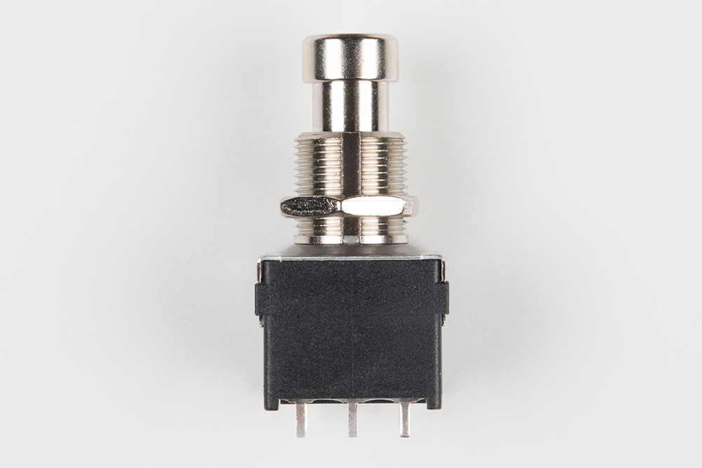
Put the lock washer on the switch, then put the switch through the chassis. On the external side of the switch, put on the smooth washer, and finally the other nut.
Tighten the nuts on the jacks and switch so they stay in place but can still rotate in the holes. Having a little bit of play in them helps get the PCB aligned properly.
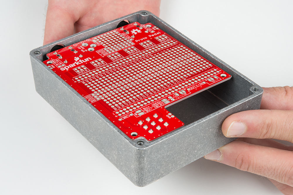
Slide the printed circuit board onto the legs of the jacks and switch.
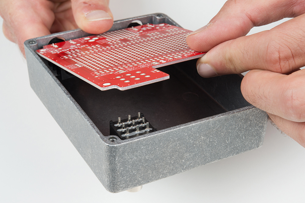
Taking care to keep the TRS jacks near the top of the oblong holes, tighten the nuts on the jacks and switch with your fingers. Due to the sloped side of the enclosure, the legs of the jacks that are nearer the center of the board will protrude further than those near the edge.
Solder the jacks and switch to the PCB.
Remove the PCB from the chassis, and put on the last few touches.
To remove the PCB from the chassis, undo the nuts on the jacks and switch. Then, press the switch, and the whole assembly will pop free.

Power Input Jack
The next step is soldering the barrel jack, which goes between the TRS jacks.
5mm LED.
If you're adding a through-hole LED, it goes next to the stomp switch, and the bias resistor goes next to it in the resistor location marked BRT. To make it through the hole in the chassis, the LED needs to stand some distance from the PCB. As with the switch and jacks, you can use the chassis as a template to get it aligned correctly.
The LED is polarized and needs to be installed correctly. The cathode of the LED is marked by both the flat spot on the collar of the LED and the shorter leg, which should face towards the switch.

With the LED and resistor soldered in place, trim the legs flush with the bottom of the PCB.
You can also remove the solder blob from SJ1, near the bias resistor, to disable the internal LED.
Chassis Ground Lug
Next, add the ground lug.
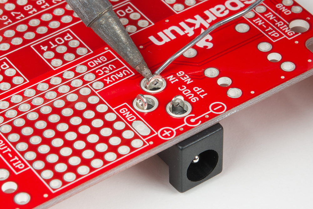
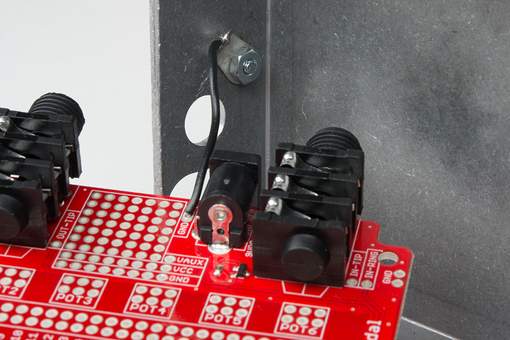
You'll need a short piece of stranded hookup wire. Strip and tin the ends of the wire. Solder one end to the ground pad near the barrel jack and the other end to the star washer.

The star washer mounts to the chassis via the small hole near the barrel jack.
9V Battery Snap
Finally, solder in the 9V battery snap. The PCB has some additional holes to relieve stress on the battery wires -- feed the wires up through the holes, then back through the solder pads. Take care to match the wires, red, and black, to the legend on the board.
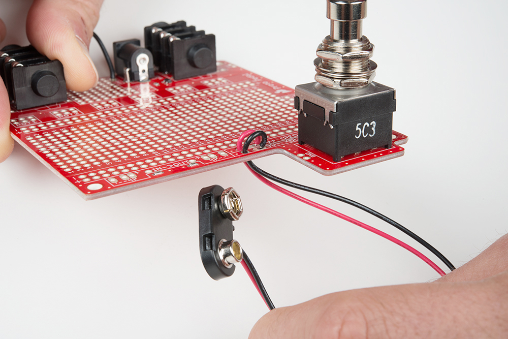
The battery snap is optional -- if you're strictly using an external power supply, you might prefer to leave it off so there isn't a loose connector wandering around in the box.