Photon Weather Shield Hookup Guide V11
This Tutorial is Retired!
This tutorial covers concepts or technologies that are no longer current. It's still here for you to read and enjoy, but may not be as useful as our newest tutorials.
 Joel_E_B
Hardware Overview
The Photon Weather Shield has a lot of functionality packed into one tiny package. Let's go over each section of the shield.
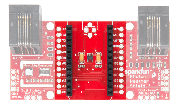
Photon Footprint
Both the Core and the Photon fit right onto the shield. Copper pours underneath the antenna were restricted so as not to interfere with wireless connections. Each pin is also broken out to the sides of the Photon for accessibility. When attaching a Photon, be sure to line up the beveled end of the Photon with the beveled silkscreen on the PCB.
Power
The simplest way to power the shield is to attach a Photon, and then power the Photon through the micro USB connector. This will power the Photon as well as all the components on the shield.
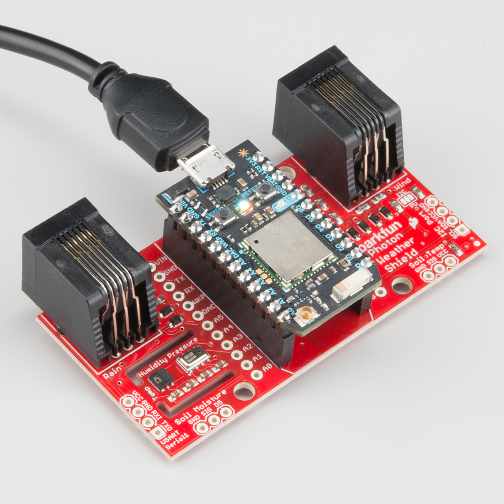
The downside to that power scheme is that micro USB connectors tend to be fragile when put under a lot of mechanical stress, and they can rip right off the PCB if pulled too hard. Thus, we provided a few other options for power connectors.
On the underside of the shield, you'll find a footprint for both an SMD Barrel Jack and a 2-pin, 3.5mm screw terminal. Either of these can be soldered to the PCB and used for alternate power inputs. The maximum voltage supplied on these alternate connectors should not exceed 12V. For a detailed explanation, read on.

For the screw terminal, you can solder it to either side of the shield, since it fits underneath the Photon. Be sure to keep track of which pin is (+) and which is (-).

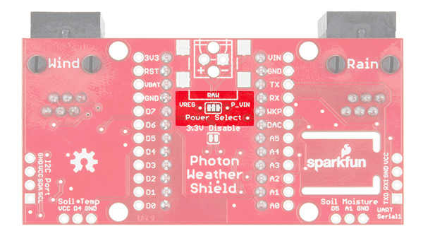
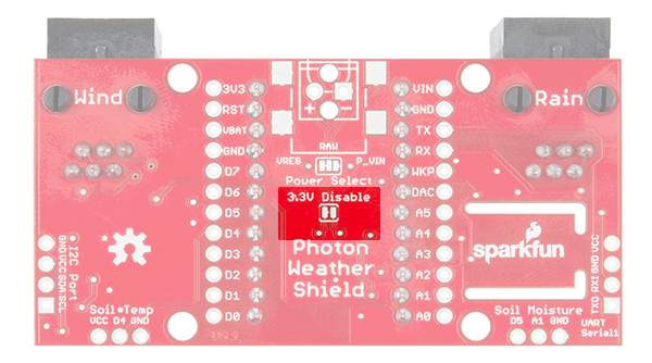
On-Board 3.3V Regulator and Power Solder Jumpers
There is also a 3.3V regulator on the shield. If you are powering the Photon through the micro USB connector, this regulator is bypassed. Powering through one of the alternative power connectors mentioned above routes power through the shield's 3.3V regulator, which is then tied to the 3.3V rail on the Photon, powering it as well.
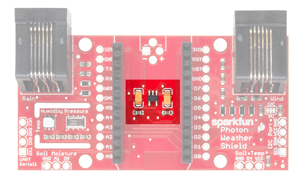
The main benefit to using the on-board regulator is that is has a higher maximum voltage rating than the regulator located on the Photon. As stated in the Photon datasheet, if power is supplied directly to the VIN pin on the Photon, the voltage should be regulated between 3.6VDC and 5.5VDC. In contrast, the MIC5205 regulator is rated for 2.5VDC to 11.5VDC, as per its datasheet.
However, if you would rather have the alternative power source route power through the regulator on the Photon (for lower current consumption during sleep perhaps), simply cut the trace on the Power Select jumper (between the VREG and RAW pads), and add a blob of solder between RAW and P_VIN (Photon VIN) pads. Just be sure to not exceed voltages of 5.5-6V once this alteration has been made.
On-Board Sensors
The weather shield comes with two on-board sensors. Together, these two sensors can give you a lot of information about the environmental conditions around you or your project.
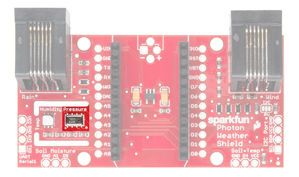
Si7021 or HTU21D Humidity and Temperature Sensor
There are two versions of the Weather Shield, one containing the HTU21D and one containing the Si7021-A10. The HTU21D can be found on older versions of the Photon Weather Shield, while the Si7021 can be found on the latest version of the shield, V11.
The Si7021 is functionally identical to the HTU21D, and they both share the same register addresses and command codes. To make it easier on the user, the Photon Weather Shield library automatically detects which sensor is present on your board without needing a separate library. More on that later.
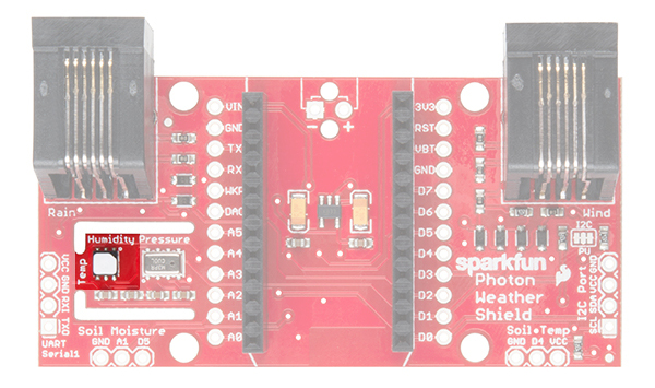
MPL3115A2 Barometric Pressure Sensor
The MPL3115A2 is a MEMS pressure sensor that provides Altitude data to within 30cm. The sensor outputs are digitized by a high-resolution 24-bit ADC and transmitted over I2C. Pressure output can be resolved with output in fractions of a Pascal, and Altitude can be resolved in fractions of a meter. It provides 12-bit temperature measurements in degrees Celsius. This sensor also communicates over I2C and comes connected to the Photon's I2C bus by default.