Photon IMU Shield Hookup Guide
 b_e_n
b_e_n 
IMU Shield Overview
Pin Descriptions
Since the shield does all of the work for you, there's no need to actually wire these connections - but in case you're looking at datasheets, or code examples, this table will give you a clue as to what the shield is doing. As always, you can check the schematic for more info.
| IMU Shield Pin | Photon Pin | Function |
|---|---|---|
| GND | GND | Ground |
| VDD | 3.3V | Regulated 3.3V in |
| SCL | D1 | SCL Serial clock |
| SDA | D0 | Serial Data in |
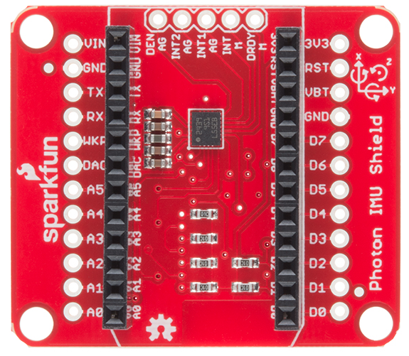
We also broke out a few pins at the top of the board that some of you may wish to make use of. From left to right in the picture above, they are:
| IMU Shield Pin | Function |
|---|---|
| DEN AG | Data Enable Accel/Gyro |
| INT2 AG | Programmable Interrupt Accel/Gyro |
| INT1 AG | Programmable Interrupt Accel/Gyro |
| INT M | Programmable Interrupt Magnetometer |
| DRDY M | Magnetic sensor data ready |
Setting the Jumpers
With the board flipped over, you'll notice there are six jumpers. The majority of these jumpers are used to switch between SPI and I2C mode. As the board ships, these jumpers are set to configure the IMU in I2C mode.
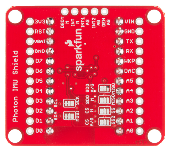
The SDO M-MISO and SDO A/G-MISO jumpers can be used to set the I2C addresses (In I2C mode) or, if open, can be used either to set I2C address or for SPI control. The default out of the box has both jumpers pulled high for I2C mode.
| SDOM /AG | AG Addr. | M Addr. |
|---|---|---|
| 0 | 0x6A | 0x1C |
| 1 | 0x6B | 0x1E |
The CS A/G-SS2 and CS M-SS are the chip select jumpers for the accelerometer/gyro and the magnetometer, respectively. The board ships with them both pulled high to enable I2C mode. Close the jumpers and cut the former traces to enable SPI mode.
The same story holds true for the SDA-MOSI and SCL-SCK jumpers. They are pulled high to enable I2C communication. Close the jumpers in the other direction and cut the former traces to enable SPI mode.