Photocell Hookup Guide
 jimblom
Example Program
Here is a simple Arduino example based on the circuit above. Copy and paste this into your Arduino IDE, then upload!
Note: This example assumes you are using the latest version of the Arduino IDE on your desktop. If this is your first time using Arduino, please review our tutorial on installing the Arduino IDE.
If you have not previously installed an Arduino library, please check out our installation guide.language:c
/******************************************************************************
Photocell_Example.ino
Example sketch for SparkFun's photocell - light-variable resistor
(https://www.sparkfun.com/products/9088)
Jim Lindblom @ SparkFun Electronics
April 28, 2016
Create a voltage divider circuit combining a photocell with a 4.7k resistor.
- The resistor should connect from A0 to GND.
- The photocell should connect from A0 to 3.3V
- Connect an LED to pin 13 (if there's not one built into your Arduino)
As the resistance of the photocell increases (surroundings get darker), the
voltage at A0 should decrease.
Development environment specifics:
Arduino 1.6.7
******************************************************************************/
const int LIGHT_PIN = A0; // Pin connected to voltage divider output
const int LED_PIN = 13; // Use built-in LED as dark indicator
// Measure the voltage at 5V and the actual resistance of your
// 47k resistor, and enter them below:
const float VCC = 4.98; // Measured voltage of Ardunio 5V line
const float R_DIV = 4660.0; // Measured resistance of 3.3k resistor
// Set this to the minimum resistance require to turn an LED on:
const float DARK_THRESHOLD = 10000.0;
void setup()
{
Serial.begin(9600);
pinMode(LIGHT_PIN, INPUT);
pinMode(LED_PIN, OUTPUT);
}
void loop()
{
// Read the ADC, and calculate voltage and resistance from it
int lightADC = analogRead(LIGHT_PIN);
if (lightADC > 0)
{
// Use the ADC reading to calculate voltage and resistance
float lightV = lightADC * VCC / 1023.0;
float lightR = R_DIV * (VCC / lightV - 1.0);
Serial.println("Voltage: " + String(lightV) + " V");
Serial.println("Resistance: " + String(lightR) + " ohms");
// If resistance of photocell is greater than the dark
// threshold setting, turn the LED on.
if (lightR >= DARK_THRESHOLD)
digitalWrite(LED_PIN, HIGH);
else
digitalWrite(LED_PIN, LOW);
Serial.println();
delay(500);
}
}
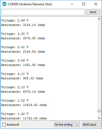
After uploading, open your serial monitor, and set the baud rate to 9600 bps.
Then trigger some changes in light; cover the photocell with your hand, turn your lights off, or shine a flashlight on the cell. You should see the voltage and resistance calculations vary with the light. If it gets darker, the resistance should go up. If it gets lighter, the resistance should go down.
R_DIV variable at the top of the sketch is set to your static resistor's value.When the sensed light gets too dark, the Arduino should turn on the pin 13 LED to try to brighten things up. By adjusting the DARK_THRESHOLD variable, you can change what lighting conditions trigger this LED illumination.