Photocell Hookup Guide
Introduction
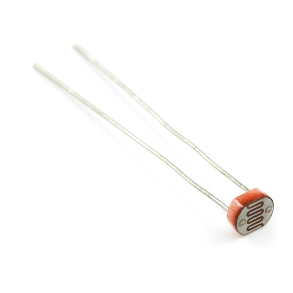
Photocells are light-sensitive, variable resistors. As more light shines of the sensor’s head, the resistance between its two terminals decreases. They're easy-to-use, and an essential component in projects that require ambient-light sensing.
In pitch-black conditions, the photocell’s resistance will be in the megaohm’s (1.0MΩ+) range. Shining an LED on the sensor can drop the resistance to near-zero, but usually the resistance of the photocell falls between 8-20kΩ in normal lighting conditions.
By combining the photocell with a static resistor to create a voltage divider, you can produce a variable voltage that can be read by a microcontroller's analog-to-digital converter.
Suggested Materials
This tutorial serves as a quick primer on resistive photocells', and demonstrates how to hook them up and use them. Beyond the light sensor, the following materials are recommended:
Arduino Uno -- We'll be using the Arduino's analog-to-digital converter to read in the variable resistance of the photocell. Any Arduino-compatible development platform -- be it a RedBoard, Pro or Pro Mini -- can substitute.
Resistor Kit -- To turn the photocell's variable resistance into a readable voltage, we'll combine it with a static resistor to create a voltage divider. This resistor kit is handy for some trial-and-error testing to hone in on the most sensitive circuit possible.
Breadboard and Jumper Wires -- The photocell's legs, like any through-hole resistor, can be bent and shaped to fit. We'll stick them and the resistor into a breadboard, then use the jumper wires to connect from breadboard to Arduino.
Suggested Reading
Photocells are a great entry-level component for beginners, but there are still a few basic electronics concepts you should be familiar with. If any of these tutorial titles sound foreign to you, consider skimming through that content first.


