$17.50
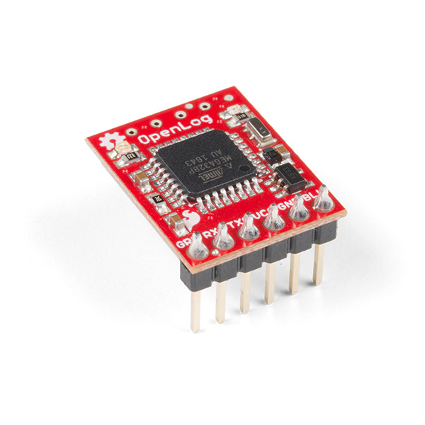
The OpenLog Data Logger is a simple-to-use, open-source solution for logging serial data from your projects. The OpenLog provides a simple serial interface to log data from a project to a microSD card.
In order to fully work through this tutorial, you will need the following parts. You may not need everything though depending on what you have. Add it to your cart, read through the guide, and adjust the cart as necessary.
If you are not familiar or comfortable with the following concepts, we recommend reading through these before continuing on with the OpenLog Hookup Guide.
The OpenLog runs at the following settings:
| VCC Input | 3.3V-12V (Recommended 3.3V-5V) |
|---|---|
| RXI Input | 2.0V-3.8V |
| TXO Output | 3.3V |
| Idle Current Draw | ~2mA-5mA (w/out microSD card), ~5mA-6mA (w/ microSD card) |
| Active Writing Current Draw | ~20-23mA (w/ microSD card) |
The OpenLog's current draw is about 20mA to 23mA when writing to a microSD. Depending on the size of the microSD card and its manufacturer, the active current draw can vary when the OpenLog is writing to the memory card. Increasing the baud rate will also pull more current.
The OpenLog runs off of an onboard ATmega328, running at 16MHz thanks to the onboard crystal. The ATmega328 has the Optiboot bootloader loaded on it, which allows the OpenLog to be compatible with the "Arduino Uno" board setting in the Arduino IDE.
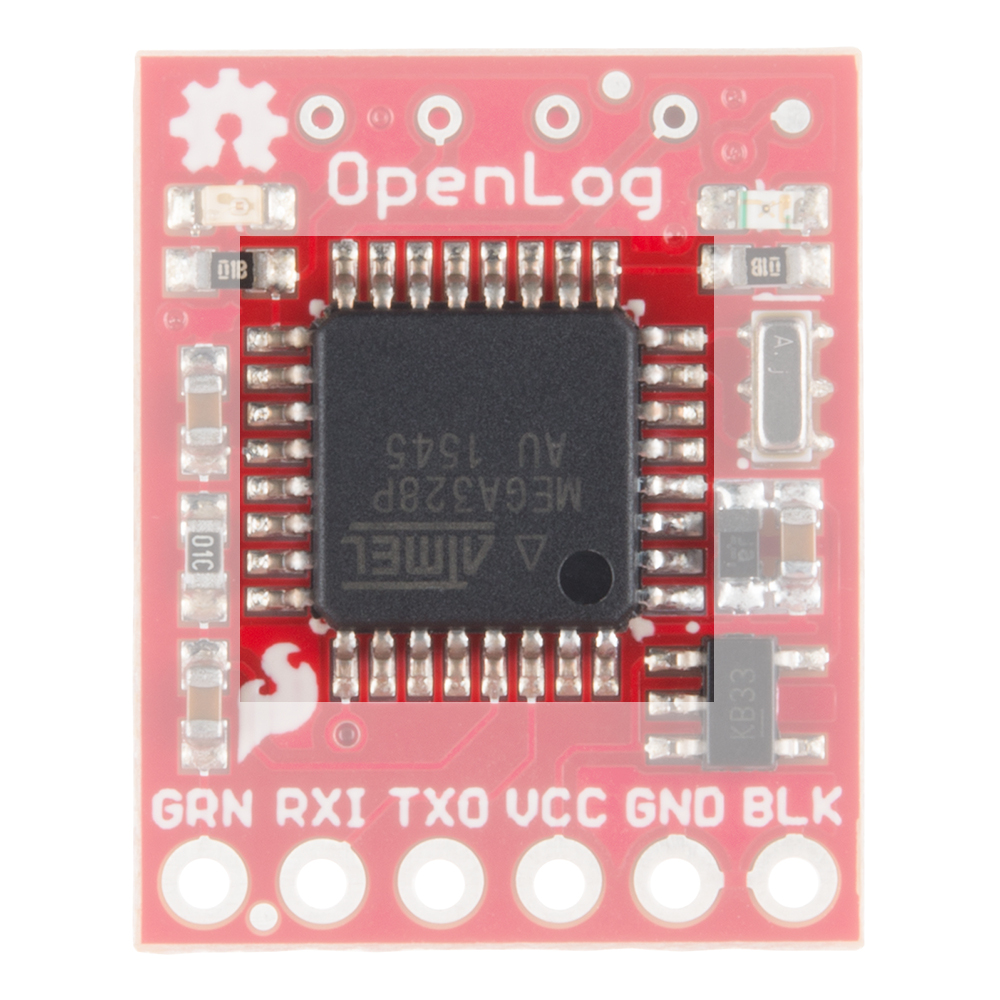
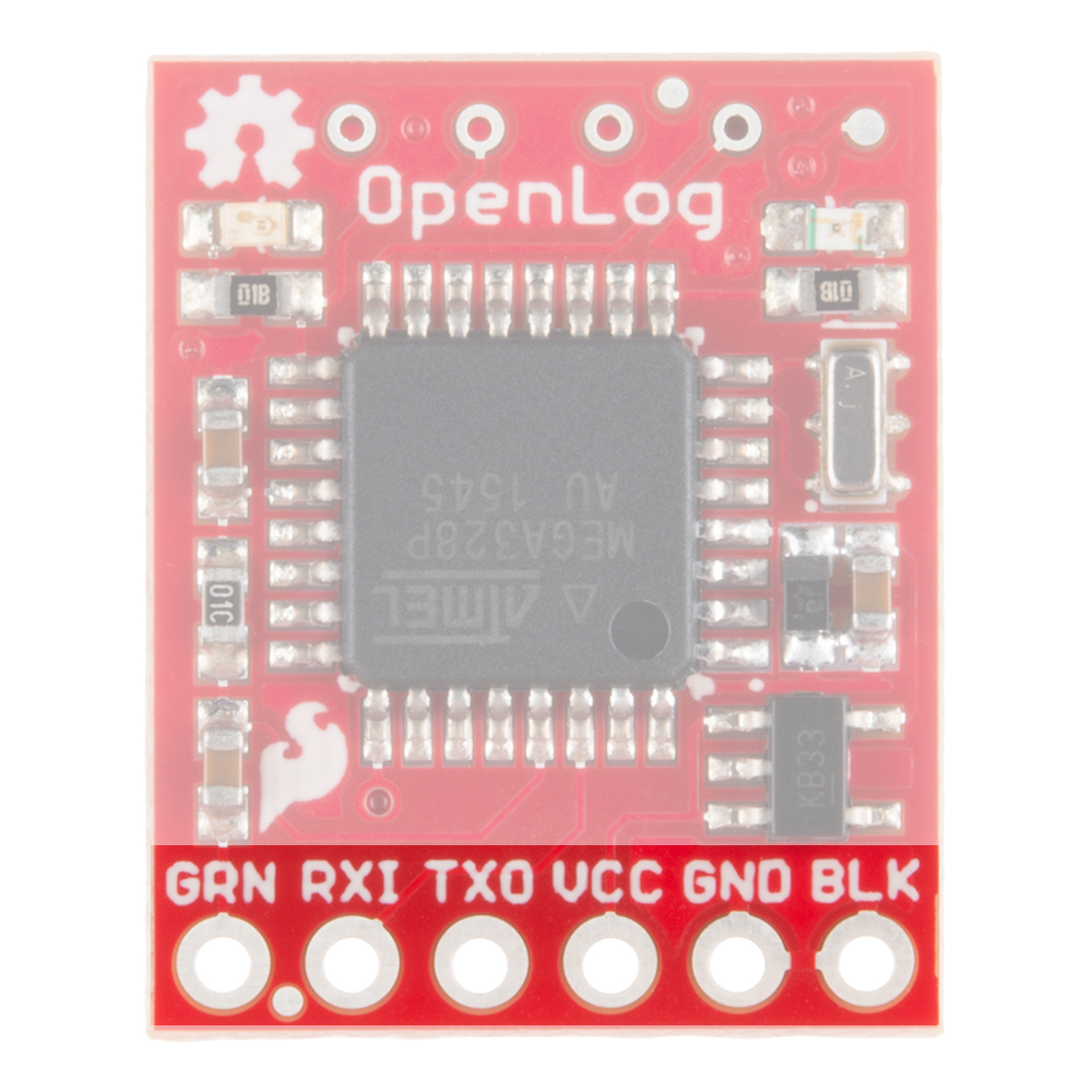
The primary interface with the OpenLog is the FTDI header on the board edge. This header is designed to plug directly into an Arduino Pro or Pro Mini, which allows the microcontroller to send the data over a serial connection to the OpenLog.
There are also four SPI test points broken out on the opposite end of the board. You can use these to reprogram the bootloader on the ATmega328.
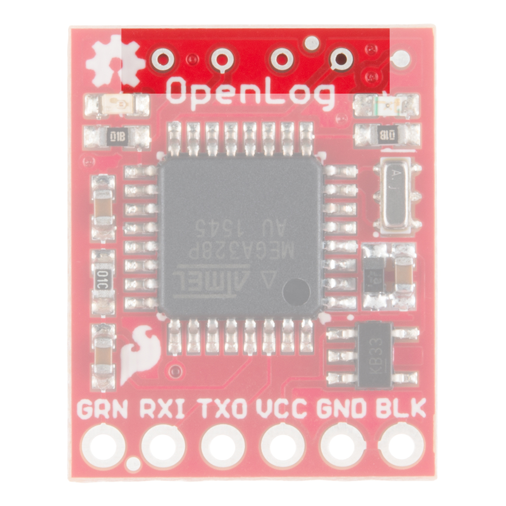
The latest OpenLog (DEV-13712) breaks out these pins on smaller plated through holes. If you need to use an ISP to reprogram or upload a new bootloader to the OpenLog, you can use pogo pins to connect to these test points.
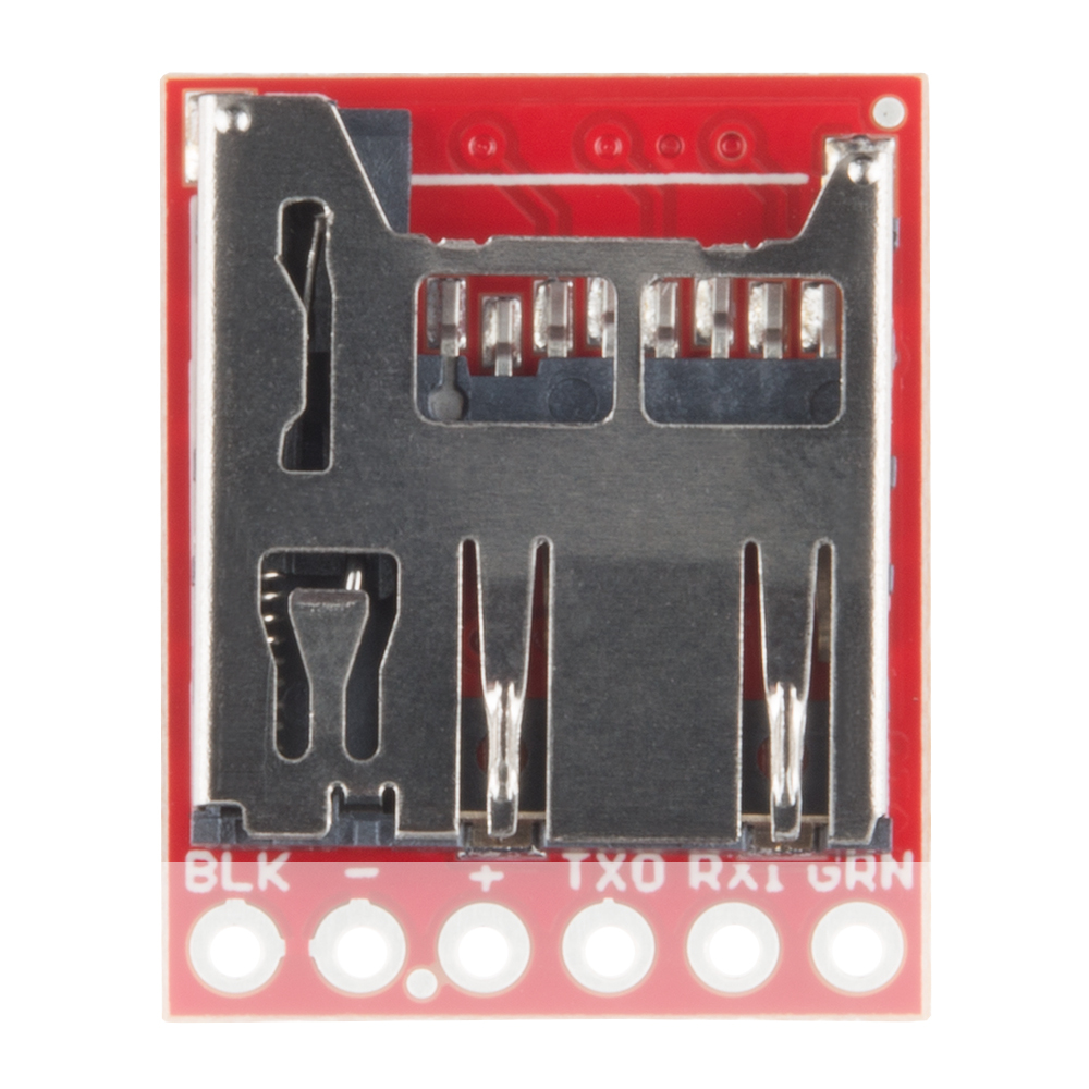
The final interface for communicating with the OpenLog is the microSD card itself. To communicate, the microSD card requires SPI pins. Not only is this where the data is stored by the OpenLog, but you can also update the OpenLog's configuration via the config.txt file on the microSD card.
All data logged by the OpenLog is stored on the microSD card. The OpenLog works with microSD cards that involve the following features:
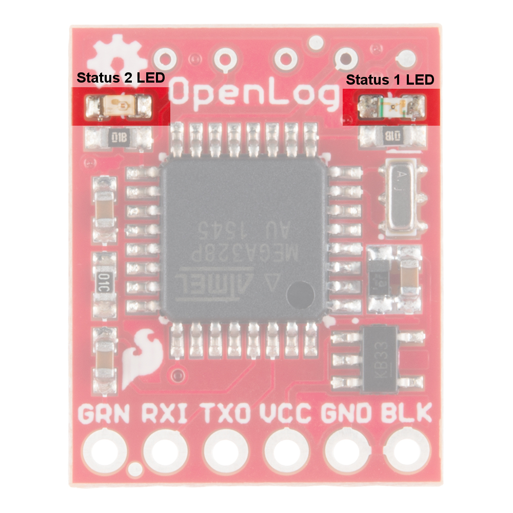
There are two status LEDs on the OpenLog to help you with troubleshooting.
There are two main methods for connecting your OpenLog to a circuit. You will need some headers or wires to connect. Make sure that you solder to the board for a secure connection.
This hardware connection is designed for interfacing with an OpenLog if you need to reprogram the board, or log data over a basic serial connection.
Make the following connections:
OpenLog → 3.3V FTDI Basic Breakout
Notice that it is not a direct connection between the FTDI and OpenLog - you must switch the TXO and RXI pin connections.
Your connections should look like the following:
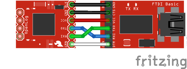
Once you have the connections between the OpenLog and the FTDI Basic, plug your FTDI board into a USB cable and into your computer.
Open up a serial terminal, connect to the COM port of your FTDI Basic, and go to town!
While interfacing with the OpenLog over a serial connection is important for reprogramming or debugging, the place where OpenLog shines is in an embedded project. This general circuit is how we recommend you hook up your OpenLog to a microcontroller (in this case, an Arduino Pro Mini) that will write serial data out to the OpenLog.
First you will need to upload the code to your Pro Mini you intend to run. Please check out the Arduino Sketches for some example code that you can use.
Once you have programmed your Pro Mini, you can remove the FTDI board, and replace it with the OpenLog. Make sure to connect the pins labeled BLK on both the Pro Mini and OpenLog (the pins labeled GRN on both will also match up if done correctly).
If you cannot plug the OpenLog directly into the Pro Mini (due to mismatched headers or other boards in the way), you can use jumper wires and make the following connections.
OpenLog → Arduino Pro/Arduino Pro Mini
Once you're finished, your connections should look like the following with the Arduino Pro Mini and Arduino Pro. The Fritzing diagram shows the OpenLogs with the headers mirrored. If you flip the microSD socket relative to the Arduino's top view, they should match the programming header like an FTDI.
 |
 |
Power up your system, and you are ready to start logging!
There are six different examples sketches included that you can use on the Arduino when connected to an OpenLog.
The OpenLog has two primary pieces of software on board: the bootloader and the firmware.
As mentioned previously, the OpenLog has the Optiboot serial bootloader on board. You can treat the OpenLog just like an Arduino Uno when uploading example code or new firmware to the board.
If you end up bricking your OpenLog and need to reinstall the bootloader, you will also want to upload Optiboot onto the board. Please check out our tutorial on installing an Arduino Bootloader for more information.
If for any reason you need to update or reinstall the firmware on your OpenLog, the following process will get your board up and running.
First, please download the Arduino IDE v1.6.5. Other versions of the IDE may work to compile the OpenLog firmware, but we have verified this as a known good version.
Next, download the OpenLog firmware and required libraries bundle.
Once you have the libraries and firmware downloaded, install the libraries into Arduino. If you are unsure how to manually install the libraries in the IDE, please check out our tutorial: Installing an Arduino Library: Manually Installing a Library.
Next, to take advantage of the modified libraries, modify the SerialPort.h file found in \Arduino\Libraries\SerialPort directory. Change BUFFERED_TX to 0 and ENABLE_RX_ERROR_CHECKING to 0. Save the file, and open up the Arduino IDE.
If you haven't yet, connect your OpenLog to the computer via an FTDI board. Please double check the example circuit if you are not sure how to do this properly.
Open the OpenLog sketch you would like to upload under Tools>Board menu, select the "Arduino/Genuino Uno", and select the proper COM port for your FTDI board under Tools>Port.
Upload the code.
That's it! Your OpenLog is now programmed with new firmware. You can now open up a serial monitor and interact with the OpenLog. On power up, you will see either 12> or 12<. 1 indicates the serial connection is established, 2 indicates the SD card has successfully initialized, < indicates OpenLog is ready to log any received serial data and > indicates OpenLog is ready to receive commands.
There are three included sketches you can use on the OpenLog, depending on your particular application.
? command will show the firmware version loaded onto a unit.You can interface with the OpenLog via a serial terminal. The following commands will help you read, write, and delete files, as well as change the settings of the OpenLog. You will need to be in Command Mode in order to use the following settings.
While the OpenLog is in Command Mode, STAT1 will toggle on/off for every character received. The LED will stay on until the next character is received.
new File- Creates a new file named File in the current directory. Standard 8.3 filenames are supported. For example, "87654321.123" is acceptable, while "987654321.123" is not.
new file1.txtappend File - Append text to the end of File. Serial data is then read from the UART in a stream and adds it to the file. It is not echoed over the serial terminal. If File does not exist when this function is called, the file will be created.
append newfile.csvwrite File OFFSET - Write text to File from the location OFFSET within the file. The text is read from the UART, line by line and echoed back. To exit this state, send an empty line.
write logs.txt 516rm File - Deletes File from the current directory. Wildcards are supported.
rm README.txtsize File - Output size of File in bytes.
size Log112.csv11read File + START+ LENGTH TYPE - Output the content of File starting from START and going for LENGTH. If START is omitted, the entire file is reported. If LENGTH is omitted, the entire contents from the starting point is reported. If TYPE is omitted, the OpenLog will default to reporting in ASCII. There are three output TYPEs:
You may leave off some trailing arguments. Check the following examples.
Basic read + omitted flags:
read LOG00004.txtAccelerometer X=12 Y=215 Z=317Read from start 0 with length of 5:
read LOG00004.txt 0 5AccelRead from position 1 with a length of 5 in HEX:
read LOG00004.txt 1 5 263 63 65 6CRead from position 0 with a length of 50 in RAW:
read LOG00137.txt 0 50 3André-- -þ Extended Character Testcat File - Write the content of a file in hex to the serial monitor for viewing. This is sometimes helpful to see that a file is recording correctly without having to pull the SD card and view the file on a computer.
cat LOG00004.txt00000000: 41 63 65 6c 3a 20 31ls - Lists all contents of the current directory. Wildcards are supported.
ls\srcmd Subdirectory - Create Subdirectory in the current directory.
md Example_Sketchescd Subdirectory - Change to Subdirectory.
cd Hello_Worldcd .. - Change to a lower directory in the tree. Note that there is a space between 'cd' and '..'. This allows the string parser to see the cd command.
cd ..rm Subdirectory - Deletes Subdirectory. The directory must be empty for this command to work.
rm tempsrm -rf Directory - Deletes Directory and any files contained within it.
rm -rf Libraries? - This command will pull up a list of available commands on the OpenLog.
disk - Show card manufacturer ID, serial number, manufacture date and card size. Example output is:
Card type: SD2
Manufacturer ID: 3
OEM ID: SD
Product: SU01G
Version: 8.0
Serial number: 39723042
Manufacturing date: 1/2010
Card Size: 965120 KB
init - Reinitialize the system and reopen the SD card. This is helpful if the SD card stops responding.
sync - Synchronizes the current contents of the buffer to the SD card. This command is useful if you have less than 512 characters in the buffer and want to record those on the SD card.
reset - Jumps OpenLog to location zero, reruns bootloader and then init code. This command is helpful if you need to edit the config file, reset the OpenLog and start using the new configuration. Power cycling is still the preferred method for resetting the board, but this option is available.
These settings can be manually updated, or edited in the config.txt file.
echo STATE - Changes the state of the system echo, and is stored in system memory. STATE can either be on or off. While on, the OpenLog will echo received serial data on the command prompt. While off, the system does not read back received characters.verbose STATE - Changes the state of verbose error reporting. STATE can either be on or off. This command is stored in memory. By turning off verbose errors, OpenLog will respond with only a ! if there is an error rather than unknown command: COMMAND. The ! character is easier for embedded systems to parse than the full error. If you are using a terminal, leaving verbose on will allow you to see full error messages.
baud - This command will open up a system menu allowing the user to enter a baud rate. Any baud rate between 300bps and 1Mbps is supported. The baud rate selection is immediate, and the OpenLog requires a power cycle for the settings to take effect. The baud rate is stored to EEPROM and is loaded every time OpenLog powers up. The default is 9600 8N1.
set - This command opens a system menu to select the boot up mode. These settings will occur at the next power-on and are stored in non-volatile EEPROM.
1 (UART is alive), 2 (SD card is initialized), then < (OpenLog is ready to receive data). All data will be recorded to a LOG#####.txt. The ##### number increases every time OpenLog powers up (the max is 65533 logs). The number is stored in EEPROM and can be reset from the set menu. All received characters are not echoed. You can exit this mode and enter command mode by sending CTRL+z (ASCII 26). All buffered data will be stored.Append File Logging - Also known as sequential mode, this mode creates a file called SEQLOG.txt if it is not already there, and appends any received data to the file. OpenLog will transmit 12< at which time OpenLog is ready to receive data. Characters are not echoed. You can exit this mode and enter command mode by sending CTRL+z (ASCII 26). All buffered data will be stored.
Command Prompt - OpenLog will transmit 12> at which time the system is ready to receive commands. Note that the > sign indicates OpenLog is ready to receive commands, not data. You can create files and append data to files, but this requires some serial parsing (for error checking), so we do not set this mode by default.
Reset New File Number - This mode will reset the log file number to LOG000.txt. This is helpful if you have recently cleared out a microSD card and want the log file numbers to start over again.
New Escape Character - This option allows the user to enter a character such as CTRL+z or $, and set this as the new escape character. This setting is reset to CTRL+z during an emergency reset.
Number of Escape Characters - This option allows the user to enter a character (such as 1, 3, or 17), updating the new number of escape characters needed to drop to command mode. For example, entering 8 will require the user to hit CTRL+z eight times to get to command mode. This setting is reset to 3 during an emergency reset.
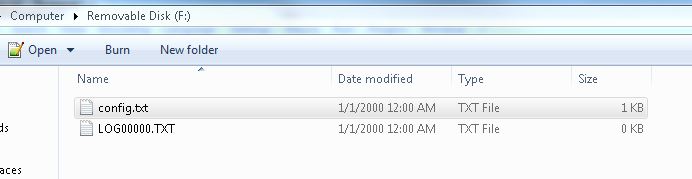
If you would rather not use the serial terminal for modifying the settings on your OpenLog, you can also update the settings by modifying the CONFIG.TXT file.
To do this, you will need a microSD card reader and a text editor. Open up the config.txt file (the capitalization of the file name does not matter), and configure away! If you have never powered up your OpenLog with the SD card before, you can also manually create the file. If you have powered up the OpenLog with the microSD card inserted previously, you should see something like the following when you read the microSD card.
The default configuration file has one line of settings and one line of definitions.
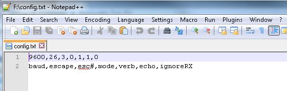
Note that these are regular visible characters (there are no non-visible or binary values), and each value is separated by a comma.
The settings are defined as follows:
baud: The communication baud rate. 9600bps is default. Acceptable values that are compatible with the Arduino IDE are 2400, 4800, 9600, 19200, 38400, 57600, and 115200. You can use other baud rates, but you will be unable to communicate with the OpenLog through the Arduino IDE serial monitor.
escape: The ASCII value (in decimal format) of the escape character. 26 is CTRL+z and is default. 36 is $ and is a commonly used escape character.
esc#: The number of escape characters required. By default, it is three, so you must hit the escape character three times to drop to command mode. Acceptable values are from 0 to 254. Setting this value to 0 will disable escape character checking completely.
mode: System mode. OpenLog starts in New Log mode(0) by default. Acceptable values are 0=New Log, 1= Sequential Log, 2 = Command Mode.
verb: Verbose mode. Extended (verbose) error messages are turned on by default. Setting this to 1 turns on verbose error messages (such as unknown command: remove !). Setting this to 0 turns off verbose errors but will respond with a ! if there is an error. Turning off verbose mode is handy if you are trying to handle errors from an embedded system.
echo: Echo mode. While in command mode, characters are echoed by default. Setting this to 0 turns off character echo. Turning this off is handy if handling errors and you don't want sent commands being echoed back to the OpenLog.
ignoreRX: Emergency Override. Normally, OpenLog will emergency reset when the RX pin is pulled low during power up. Setting this to 1 will disable the checking of the RX pin during power up. This can be helpful for systems that will hold the RX line low for various reasons. If Emergency Override is disabled, you will not be able to force the unit back to 9600bps, and the configuration file will be the only way to modify the baud rate.
There are five different situations for the OpenLog to modify the config.txt file.
Config file found: During power up, OpenLog will look for a config.txt file. If the file is found, OpenLog will use the included settings and overwrite any previously stored system settings.
No config file found: If OpenLog cannot find the config.txt file then OpenLog will create config.txt and record the currently stored system settings to it. This means if you insert a newly formatted microSD card, your system will maintain its current settings.
Corrupt config file found: OpenLog will erase the corrupted config.txt file, and will rewrite both the internal EEPROM settings and the config.txt settings file to the known-good state of 9600,26,3,0,1,1,0.
Illegal values in config file: If the OpenLog discovers any settings containing illegal values, OpenLog will overwrite the corrupt values in config.txt file with the currently stored EEPROM system settings.
Changes through command prompt: If the system settings are changed through the command prompt (either over a serial connection or via microcontroller serial commands) those changes will be recorded both to the system EEPROM and to the config.txt file.
Emergency Reset: If the OpenLog is power cycled with a jumper between RX and GND, and the Emergency Override bit is set to 0 (allowing emergency reset), OpenLog will rewrite both the internal EEPROM settings and the config.txt settings file to the known-good state of 9600,26,3,0,1,1,0.
There are several different options to check if you are having issues connecting over the serial monitor, having issues with dropped characters in logs, or fighting a bricked OpenLog.
STAT1 LED shows different behavior for two different common errors.
If you are using the default OpenLog.ino example, OpenLog will only support two subdirectories. You will need to change FOLDER_TRACK_DEPTH from 2 to the number of subdirectories you need to support. Once you've done this, recompile the code up, and upload the modified firmware.
OpenLog will only support up to 65,534 log files in the root directory. We recommend reformatting your microSD card to improve logging speed.
If you are writing a custom sketch for the OpenLog, verify that your sketch is not larger than 32,256. If so, it will cut into the upper 500 bytes of Flash memory, which is used by the Optiboot serial bootloader.
All file names should be alpha-numeric. MyLOG1.txt is ok, but Hi !e _.txt may not work.
OpenLog runs off of the ATmega328 and has a limited amount of RAM(2048 bytes). When you send serial characters to OpenLog, these characters get buffered. The SD Group Simplified Specification allows an SD card to take up to 250 ms (section 4.6.2.2 Write) to record a data block to flash memory.
At 9600 bps, that's 960 bytes (10 bits per byte) per second. That is 1.04 ms per byte. OpenLog currently uses a 512 byte receive buffer so it can buffer around 500 ms of characters. This allows OpenLog to successfully receive all characters coming at 9600 bps. As you increase the baud rate, the buffer will last for less time.
| Baud Rate | Time per byte | Time Until Buffer is Overrun |
|---|---|---|
| 9600 bps | 1.04 ms | 532 ms |
| 57600 bps | 0.174 ms | 88 ms |
| 115200 bps | 0.087 ms | 44 ms |
Remember to use a card with few or no files on it. A microSD card with 3.1GB worth of ZIP files or MP3s has a slower response time than an empty card.
If you did not format your microSD card on a Windows OS, reformat the microSD card and create a DOS filesystem on the SD card.
There are many different types of card manufacturers, relabeled cards, card sizes, and card classes, and they may not all work properly. We typically use an 8GB class 4 microSD card, which works well at 9600bps. If you need higher baud rates, or larger storage space, you may want to try class 6 or above cards.
By adding a small delay between Serial.print() statements, you can give OpenLog a chance to record its current buffer.
For example:
language:c
Serial.begin(115200);
for(int i = 1 ; i < 10 ; i++) {
    Serial.print(i, DEC);
    Serial.println(":abcdefghijklmnopqrstuvwxyz-!#");
}
may not log properly, as there are a lot of characters being sent right next to each other. Inserting a small delay of 15ms between large character writes will help OpenLog record without dropping characters.
language:c
Serial.begin(115200);
for(int i = 1 ; i < 10 ; i++) {
    Serial.print(i, DEC);
    Serial.println(":abcdefghijklmnopqrstuvwxyz-!#");
    delay(15);
}
If you are attempting to use the OpenLog with the built-in serial library or the SoftwareSerial library, you may notice issues with command mode. Serial.println() sends both newline AND carriage return. There are two alternative commands to overcome this.
The first is to use the \r command (ASCII carriage return):
language:c
Serial.print("TEXT\r");
Alternatively, you can send the value 13 (decimal carriage return):
language:c
Serial.print("TEXT");
Serial.write(13);
Remember, if you need to reset the OpenLog to a default state, you can reset the board by tying the RX pin to GND, powering up the OpenLog, waiting until the LEDs begin to blink in unison, and then powering down the OpenLog and removing the jumper.
If you have changed the Emergency Override bit to 1, you will need to modify the configuration file, as the Emergency Reset will not work.
If you are still having issues with your OpenLog, please check out the current and closed issues on our GitHub repository here. There is a large community working with the OpenLog, so chances are that someone has found a fix for the problem you are seeing.
Now that you've successfully logged data with your OpenLog, you can set up remote projects and monitor all the possible data coming. Consider creating your own Citizen Science project, or even a pet tracker to see what Fluffy does when out and about!
Check out these additional resources for troubleshooting, help, or inspiration for your next project.
Need some more inspiration? Check out some of these related tutorials:
Or check out these blog posts for ideas.
If you have any tutorial feedback, please visit the comments or contact our technical support team at TechSupport@sparkfun.com.
learn.sparkfun.com | CC BY-SA 3.0 | SparkFun Electronics | Niwot, Colorado