Non-Addressable RGB LED Strip Hookup Guide
 bboyho
 Hardware Hookup
We'll be using a common anode RGB LED strip. There are a few methods of lighting the LED strip:
- straight power
- 555 Timer
- pre-programmed controller box
- microcontroller/single board computer
Below are three of these methods. For the scope of this tutorial, we will be using the third circuit diagram.
Hookup 1: Straight Power!
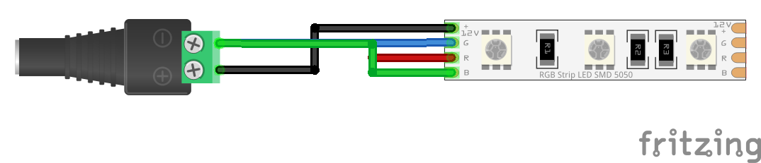
The simplest method of using non-addressable LEDs to illuminate your project is to add power to your LED strip. You will just need to make a connection between the female barrel jack adapter and the non-addressable LED strip. Simply insert the black wire connecting the "12V" pin to the "+" of the barrel jack adapter's screw terminal for power. Then insert the wire or your choice into the "-" screw terminal. In the following hookup, all channels were connected to ground to mix the color of white.
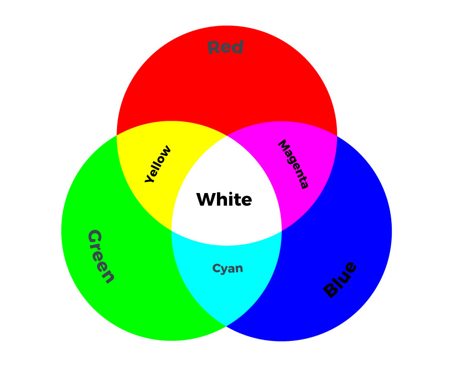
Depending on your project and color that you are illuminating, you will need to ground each respective channel. Here are some basic colors that you could mix by grounding different pins. The tradeoff is that you are limited to seven colors and will need to adjust the connection every time you need to change the color. For projects that do not require that many colors, this would be the best setup.
Hookup 2: Preprogrammed Controller Box
For those that are interested in a preprogrammed controller to easily control the non-addressable LED strip with a controller, you could use the Mi-Light remote and controller box. You will simply need to connect power through the barrel jack and tighten the screws for each channel. The controller box includes an additional "white" channel for LED strips with that have an the color.
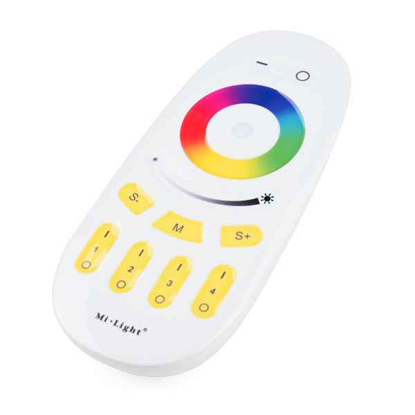
Mi-Light 4-Zone LED Remote Controller
COM-14711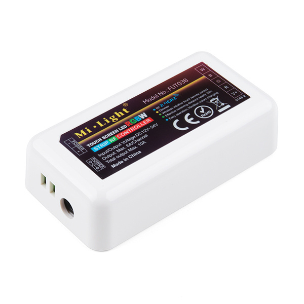
Mi-Light RGBW LED Controller Box
COM-14710For more information, check out the video below!
Hookup 3: Microcontroller
For those that want a little bit more flexibility and control over the LEDs, you can use a microcontroller. We'll be using a RedBoard Qwiic with the ATmega328P. You can use different microcontollers (i.e. AVR, ARM, micro:bit, ESP8266, ESP32, etc.) or single board computer (i.e. Raspberry Pi) as long as it can output a PWM signal. You just need a transistor since the logic level is lower than the voltage of the LED strip and the pins are not able to source enough current. The code (i.e. MakeCode, Python, etc.) depends on the microcontroller or single board computer. For the scope of the tutorial, we will be using the Arduino language to control the LEDs.
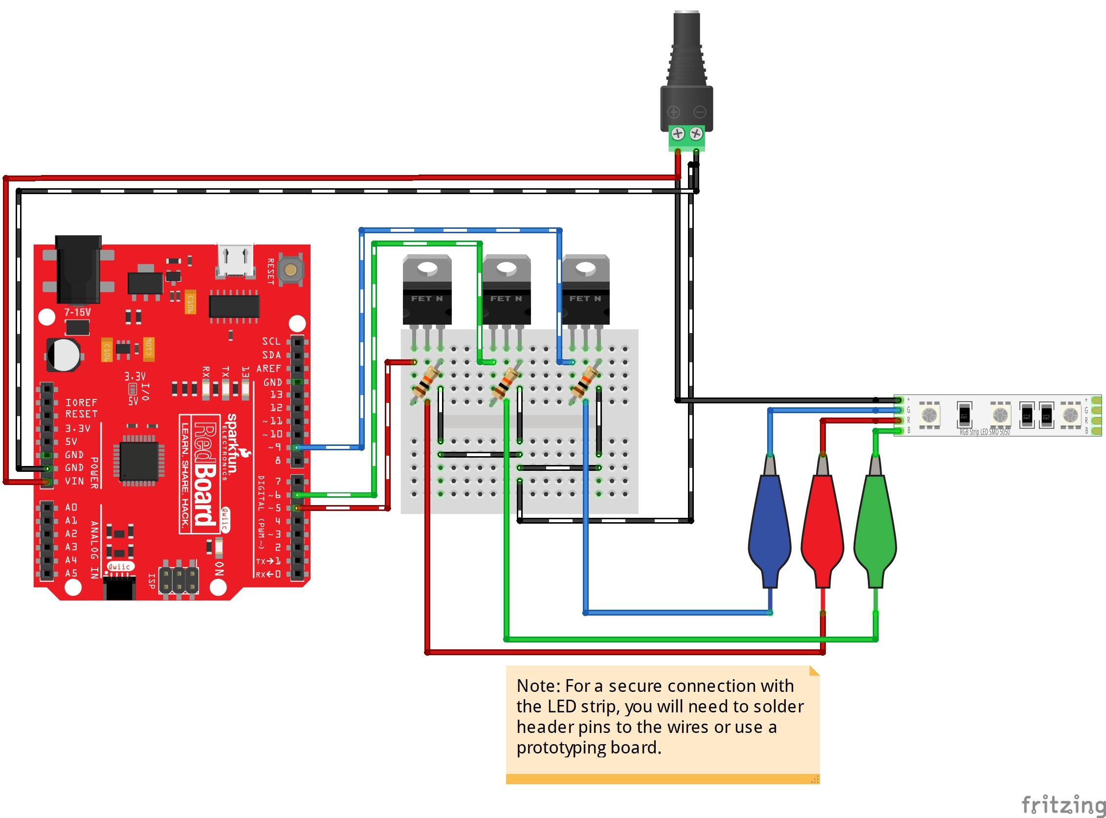
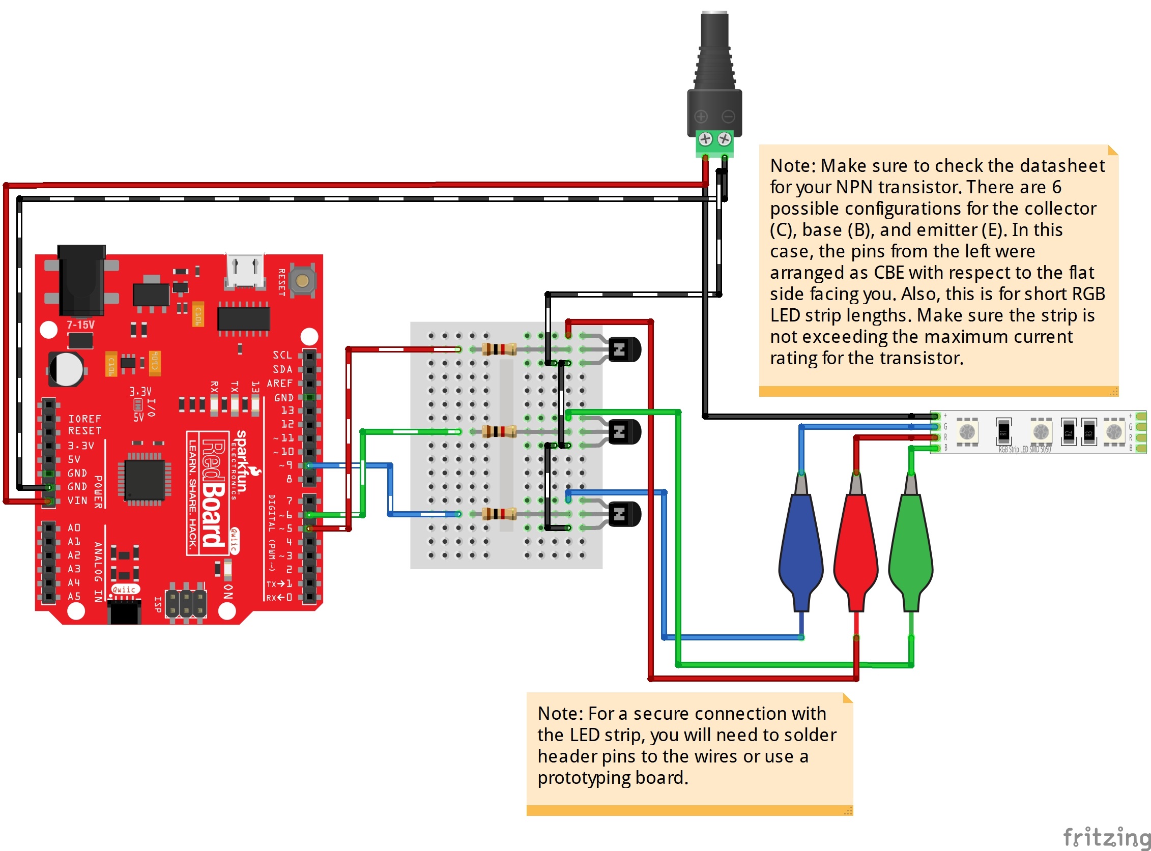
Typically for common anode RGB LED strips, you could use NPN BJTs or N-channel MOSFETs as a switch. N-channel mosfets usually can handle more power and they are more power efficient. Therefore, we'll be adding the load on the high side. Each color channel requires a transistor to switch. The hookup diagram for a basic connection is shown on the left. For additional functionality, you could add buttons and a potentiometer to control the LEDs. For testing purposes, we'll use a breadboard, jumper wires, and alligator clips to connect. You'll eventually want to solder the LED strip to header pins, a prototyping board, or splice a 4-pin pigtail connector for a secure connection when using it in an installation.
 |
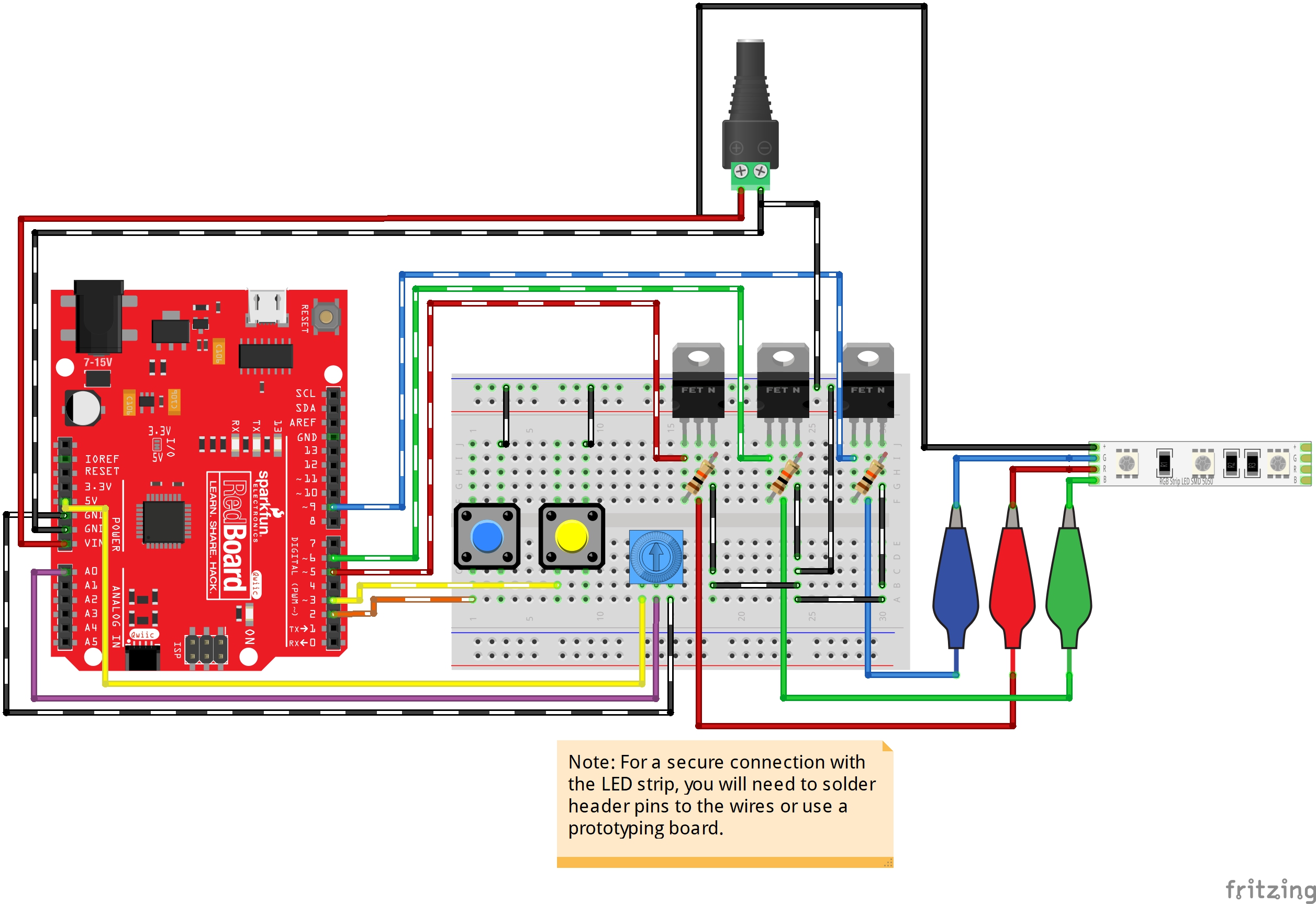 |
| Basic Arduino Hookup w/ N Channel MOSFETS | Buttons and Potentiometers Added for Additional Functionality |
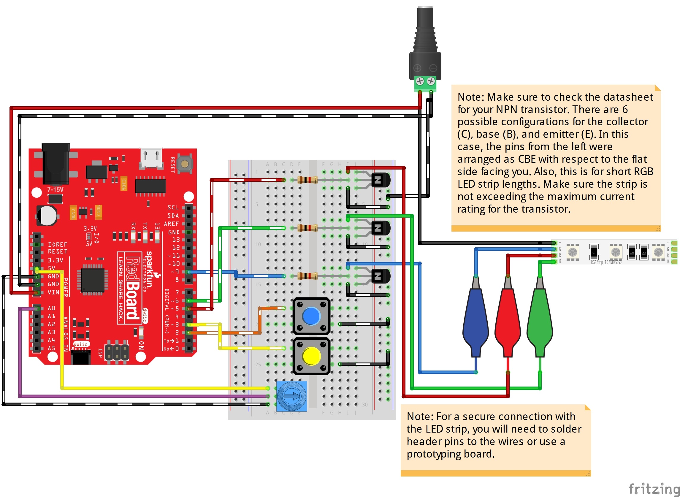
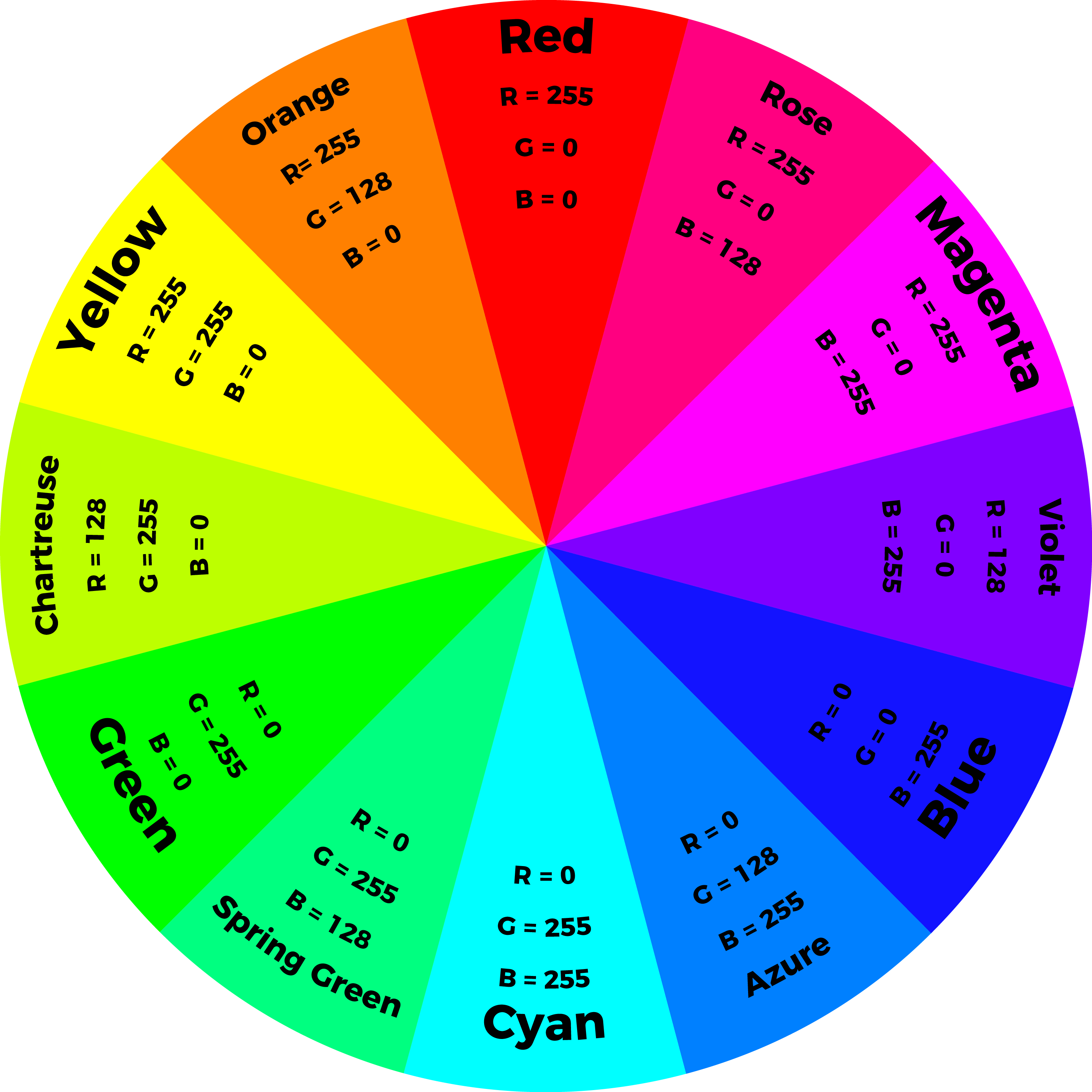
By using a PWM output from a microcontroller and transistor to adjust the brightness of each color channel individually, the RGB LED can display almost any color you choose! For simplicity, we'll limit the colors to twelve colors and white on an Arduino. The following values in the diagram will create the primary, secondary, and tertiary colors.
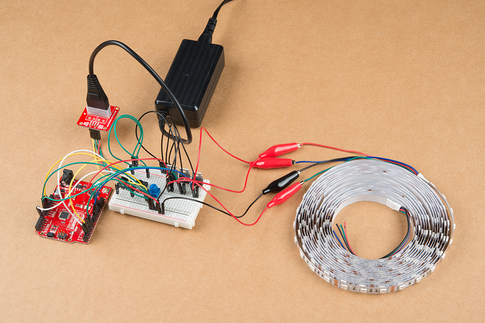
When using long strands, it is recommended to have a separate power supply for the Arduino and LEDs. Your setup should look similar to the image below on a breadboard if you are using a 12V/5V, 2A power supply and a 5M LED strip. The setup is the same except VIN is disconnected on the 12V. The Arduino is using its own 5V power. When programming the Arduino, it is recommended to disconnect the 5V pin so that you do not have conflicting power sources.
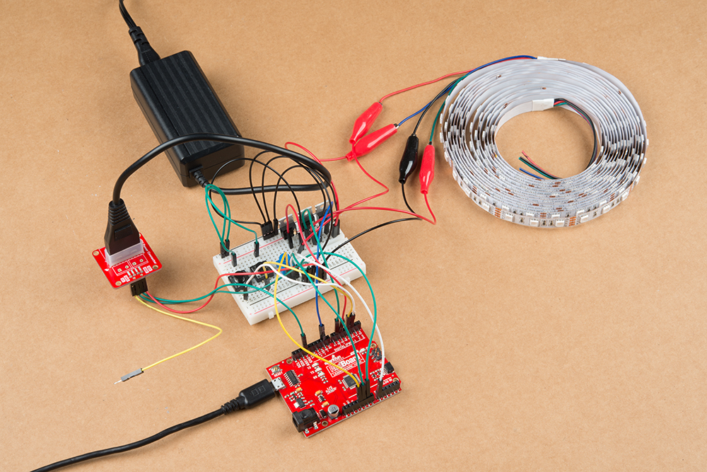
After you are done programming, you can remove the USB cable and connect the 12V/5V power supply's 5V pin to the circuit.