MP3 Player Shield Hookup Guide V15
 jimblom,
  Byron J.
Hardware Overview
The centerpiece of the MP3 Player Shield is a VS1053B Audio Codec IC. The VS1053B is a multitalented little chip. On top of MP3's, it can also decode Ogg Vorbis, AAC, WMA, and MIDI. (It's also capable of encoding audio, although that's outside the scope of the MP3 Shield.)
Supporting the VS1053B is a µSD card socket, which you can use to store MP3 files on. Using the Arduino SD library, it's simple to read music files off an SD card, and stream them to the VS1053B. There's additional circuitry on-board to level shift signals down to the 3.3V maximum allowable by SD cards.
Here's a quick visual overview of the important connectors and other components on the MP3 Player Shield:
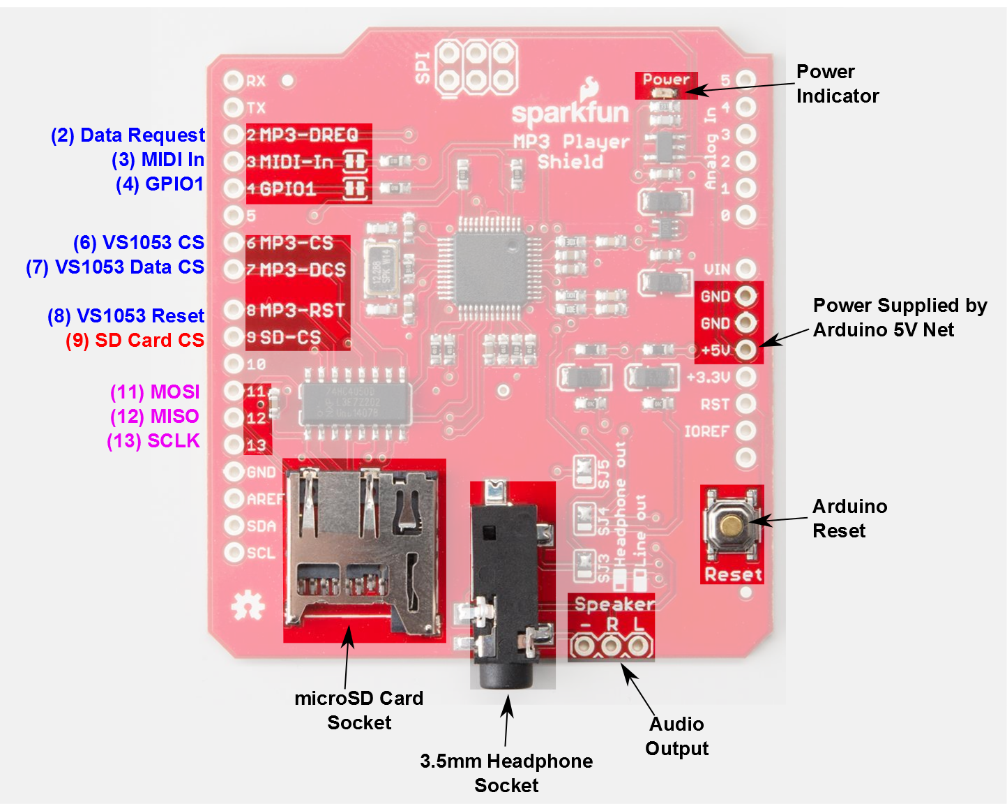
In the image above, the blue labels are pins used by the VS1053 MP3 Codec IC, the red labels are used for communication with the µSD card, and the purple-labeled pins are used by both components (yay SPI!).
Which Pins are Being Used?
The MP3 Player Shield requires exclusive use of a handful of pins. These pins can't be used to interface with other devices:
- D2 is connected to the data request output of the VS1053B. This pin is an interrupt, which tells the Arduino that the IC needs more music data.
- D6 is connected to the chip select input of the VS1053B. This active-low pin tells the chip when data is being sent to it.
- D7 is connected to the data chip select input of the VS1053B, which tells the chip when music data is being sent.
- D8 is connected to the reset input of the VS1053B.
- D9 is connected to the chip select input of the µSD card.
The Arduino's three SPI data and clock pins -- D11, D12, and D13 -- can be used to interface to other SPI components. They can't, however, be used for any purpose other than SPI.
Which Pins are Free?
Whew! The shield does use up quite a few pins, but here are the pins still available to connect to other components.
- The hardware UART pins -- RX and TX -- on pins 0 and 1
- D5 and D10 (PWM pins!)
- All analog pins (A0 through A5).
Optional Pin Jumpers
Two pins we haven't mentioned yet are D3 and D4, which are connected to the VS1053B's MIDI-In and GPIO1 pins respectively. Use of these pins is optional. They're not required for most MP3-playing functions, including the examples we'll show in this tutorial.
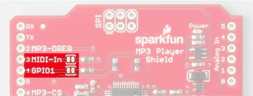
To disable either of those pins, a jumper next to their label can be cut using a hobby knife.