MP3 Player Shield Hookup Guide V15
 jimblom,
  Byron J.
Getting Audio Out
The VS1053 packs a lot of features into a tiny chip. It combines an MP3 decoder, volume control, and headphone amplifier in a single IC. It's the heart of many small MP3 Players. However, because the SparkFun MP3 Player Shield finds it's way into applications beyond portable devices, the outputs need to be more flexible. In the sections below, we'll explore how to configure the output hardware, and the reasons behind that configuration.
Output Connections
The audio outputs from the board are found on the 3.5mm headphone jack, and the adjacent set of 0.1" solder pads.
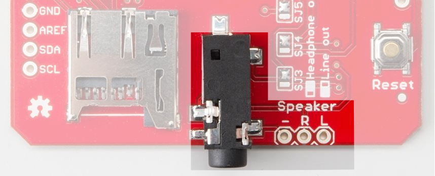
The solder pads and headphone jack are wired in parallel - the same signals are present on both the pads and the jack. They are connected as follows.
| Signal Name | Jack Connection | Pad Connection |
| Left Channel | tip | "L" |
| Right Channel | ring | "R" |
| Reference (ground or GBUF) | Sleeve | "-" |
Quick Testing
The easiest way to hear the output of the MP3 Shield is to plug a set of headphones into the 3.5mm connector. The VS1053B is rated to drive 'phones with a load impedance of 16 Ω or greater - typical headphones and earbuds are frequently 32 Ω, well above the limit.
If headphones are your desired output method, you can plug them in and skip ahead to the next section. But if you want to interface with other devices, such as a connection to your computer, an external amplifier, or larger speakers, keep reading.
Output Circuit Details
The VS1053B is designed for battery-powered applications that drive headphones. In particular, the headphone amplifier circuitry is optimized for this scenario - which makes other use cases a little harder. It's a complex enough topic that VLSI published an application note to illustrate proper interconnection.
First, let's take a closer look at how the output is tailored to driving headphones.
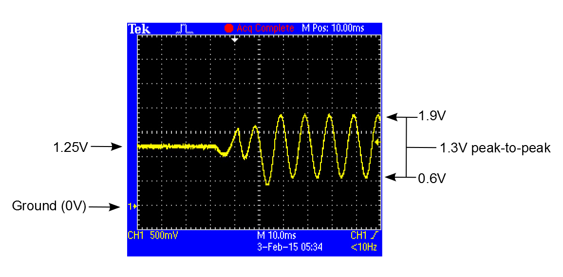
Specifically, the signals coming from the VS1053 are DC coupled. This means that the alternating-current (AC) audio signals are riding on top of a 1.25 V DC offset. The datasheet specifies that the output can swing about 2 V peak-to-peak, which results in output signals that swing between 0.25V and 2.25 V.
There are two tricky things that allow this to work. First, headphones are self-contained - they don't have any other connections to ground.
The other thing is that the VS1053B provides a special DC reference voltage output. The chip generates the "GBUF" output, held at 1.25 VDC, to be tied to the sleeve of the headphone connection. When the player is quiet, the output and the reference are both 1.25 V, so no current flows. When signal is present, it's the potential difference between the output and GBUF that makes current flow, making the drivers in the headphones move, creating sound.
In spite of the "G" in it's name, GBUF is not ground - in the pin descriptions, the datasheet specifically warns us "Common buffer for headphones, do NOT connect to ground!"
Where This Breaks Down
While this works fine for headphones, things get more complicated when we want to tie the output to other devices, especially when they have ground connections of their own. The datasheet describes the following situation:
- The player is powered via a USB connection to a PC - as we commonly do with Arduino boards. The USB jack is grounded inside the PC.
- The output from the player is plugged into the PC line input jack, using a 3.5mm cable.
As described above, the sleeve of the headphone output is the GBUF signal, with a 1.25V DC offset on it - but the sleeve of the PC line input is grounded, at 0 V.
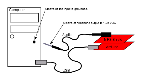
Plugging the two of them together causes a short circuit, and can potentially damage the circuitry on either end of the connection!
Engage AC-Coupling
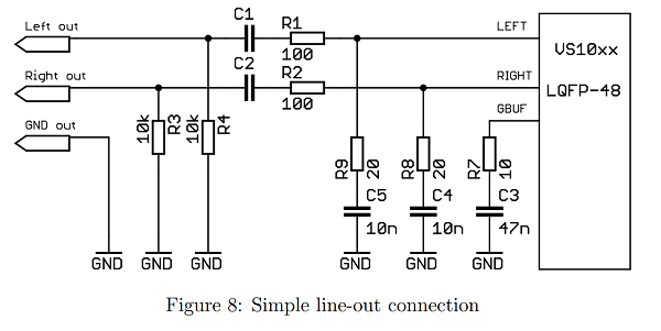
To solve this, we need to get rid of the DC voltage present on the MP3 player shield outputs. Getting rid of the DC voltage is known as AC-coupling (sometimes also called DC blocking). The AC portion of the output (the audio waveform itself) is transferred (or coupled) to the other device, but the DC offset is removed. The VS1053B application note makes several recommendations for AC-coupling the output - we implemented the circuit shown in Figure 8.
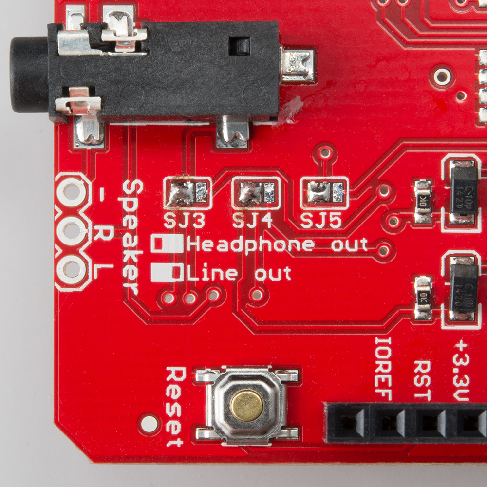
The AC-coupling circuit is enabled with solder jumpers SJ3, SJ4 and SJ5. By reconfiguring those jumpers, we can convert the outputs from a DC-coupled headphone out to an AC-coupled line output.
- SJ3 and SJ4 add 10 µF capacitors in line with the L and R outputs. The 1.25 V offset doesn't cross the caps, effectively recentering the waveforms about 0V
- SJ5 changes the sleeve and "-" terminal to connect to ground, rather than GBUF, avoiding the short circuit illustrated above
The jumpers all work together - they should all be set in the same direction.
To change the jumpers, first heat up and remove the default blobs using a solder sucker or solder wick. Then flow fresh solder onto the other pair of pads. It can be useful to verify your work with a magnifying glass, or a continuity tester.
With the jumpers swapped, the output waveforms are re-oriented around ground.
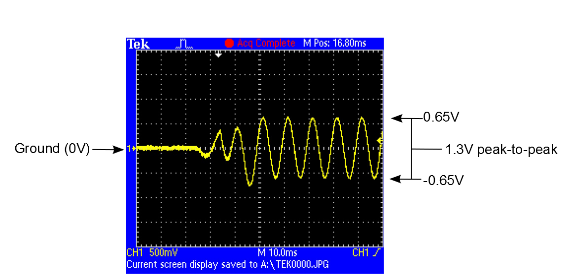
So why not just have the AC-coupling circuitry enabled all the time? There is one primary reason: the added resistors in series with the outputs make headphones much quieter than the DC-coupled configuration. This isn't an issue for line inputs, which are frequently 10kΩ or higher, but it becomes a significant voltage divider when driving low imepdance headphones. Louder is better, right?
External Speakers
If you want to make the MP3 Player Shield audible to others, you'll want to add external speakers. While you can simply plug speakers into the headphone output, the onboard circuit isn't sufficiently powerful to drive them - they'll be extremely quiet.
One simple solution that pops up here at SparkFun HQ is to simply plug the player into a set of self-powered multimedia PC speakers.
If you're looking for a DIY solution to driving speakers, consider using our Mono Audio Amp Breakout or Stereo Amplifier Kit.
Output Configuration Summarized
| To Connect | Set SJ3, SJ4, SJ5 | Additional Hardware |
| Headphones | For headphones (To the Right) | - |
| External active devices (PC, stereo reciever, powered speakers, etc) | For line out (To the Left) | - |
| Passive Speakers | For line out (To the Left) | Audio Amplifier |