microSD Sniffer Hookup Guide
 Toni_K
Hardware Overview
Hardware wise, the microSD Sniffer is pretty simple and straight-forward! There's only 3 main parts you need to be aware of.
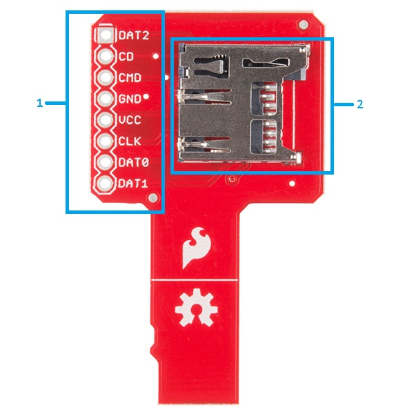
1. Headers
The pins of the SD card are broken out for a standard 0.1-inch row of header holes. This allows you to solder headers onto the board and connect into a breadboard for prototyping. Alternatively, you can also just connect IC hooks on these holes and use a logic analyzer or oscilloscope to monitor the traffic across the SPI bus.
2. microSD Socket
This is your standard microSD socket. It fits microSD cards. Hurray simplicity!
3. microSD Insert
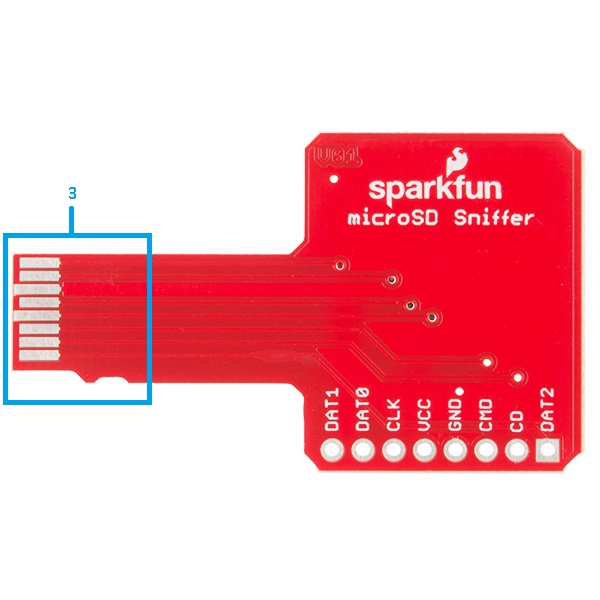
These are the actual connection pins for the microSD Sniffer. You will plug these into your circuit in place of where you would normally plug in a microSD card. Notice how they look exactly like the bottom of your microSD card?