microSD Sniffer Hookup Guide
 Toni_K
Functionality
Visualization
We can now view the data on the SPI bus with the logic analyzer. In our example, the Redboard is running the Examples>SD>Datalogger.ino sketch included by default in the Arduino IDE.
Open up the logic analyzer software, and configure it for your set up. In our example, we've labeled each channel with the corresponding pin name on the microSD Sniffer.
The analyzer collects 1 million samples at 8MHz. Once it has collected data, you should see something similar to the following.
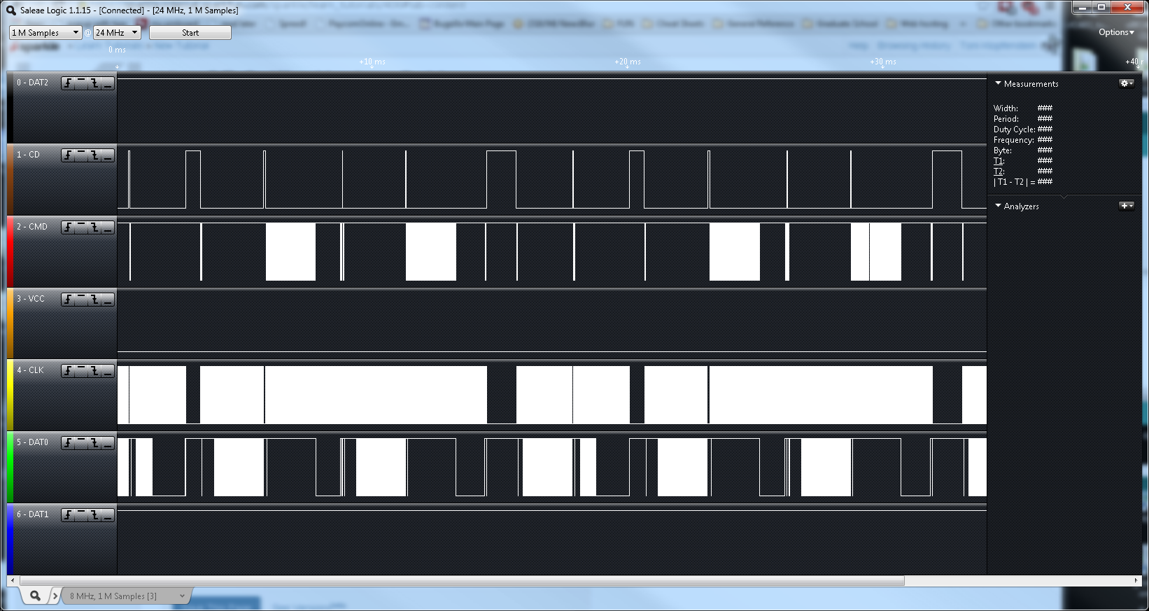
We can see there is definitely something occuring on several of the lines, but it's still not clear what. If we look at our time scale, the range shown is 0ms to ~35ms. We can zoom in on a smaller time scale to get more detail about the communication occurring.
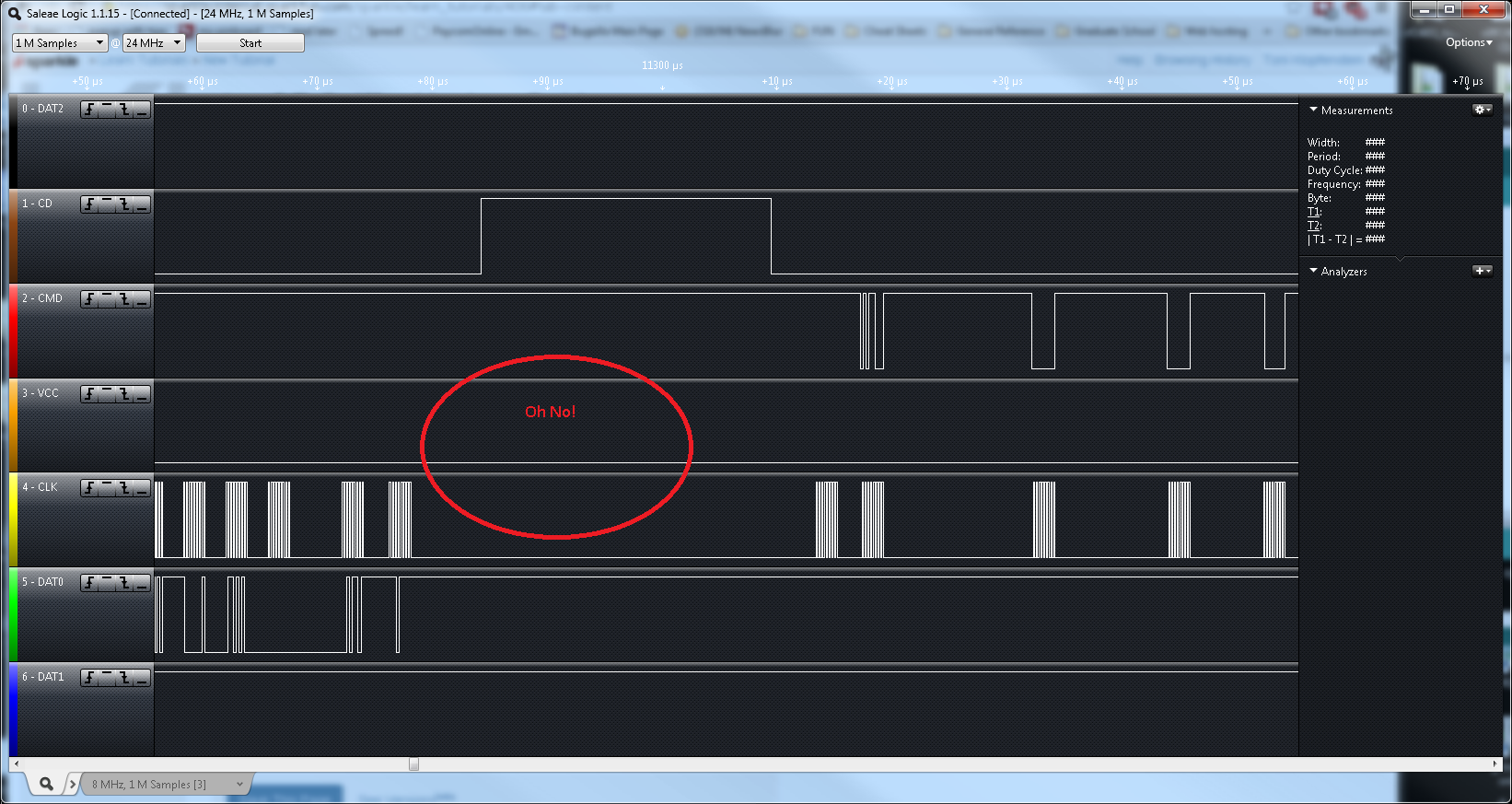
Looking at our data, we can see something is not quite right -- according to the VCC line, there's no power going to our system! While the issue in this case was only due to a loose connection between the IC hook on the analyzer and the Sniffer, you could dig deeper into each signal to debug your circuit if there is a problem. If we fix the loose connection, the data looks better, showing a HIGH signal on VCC.
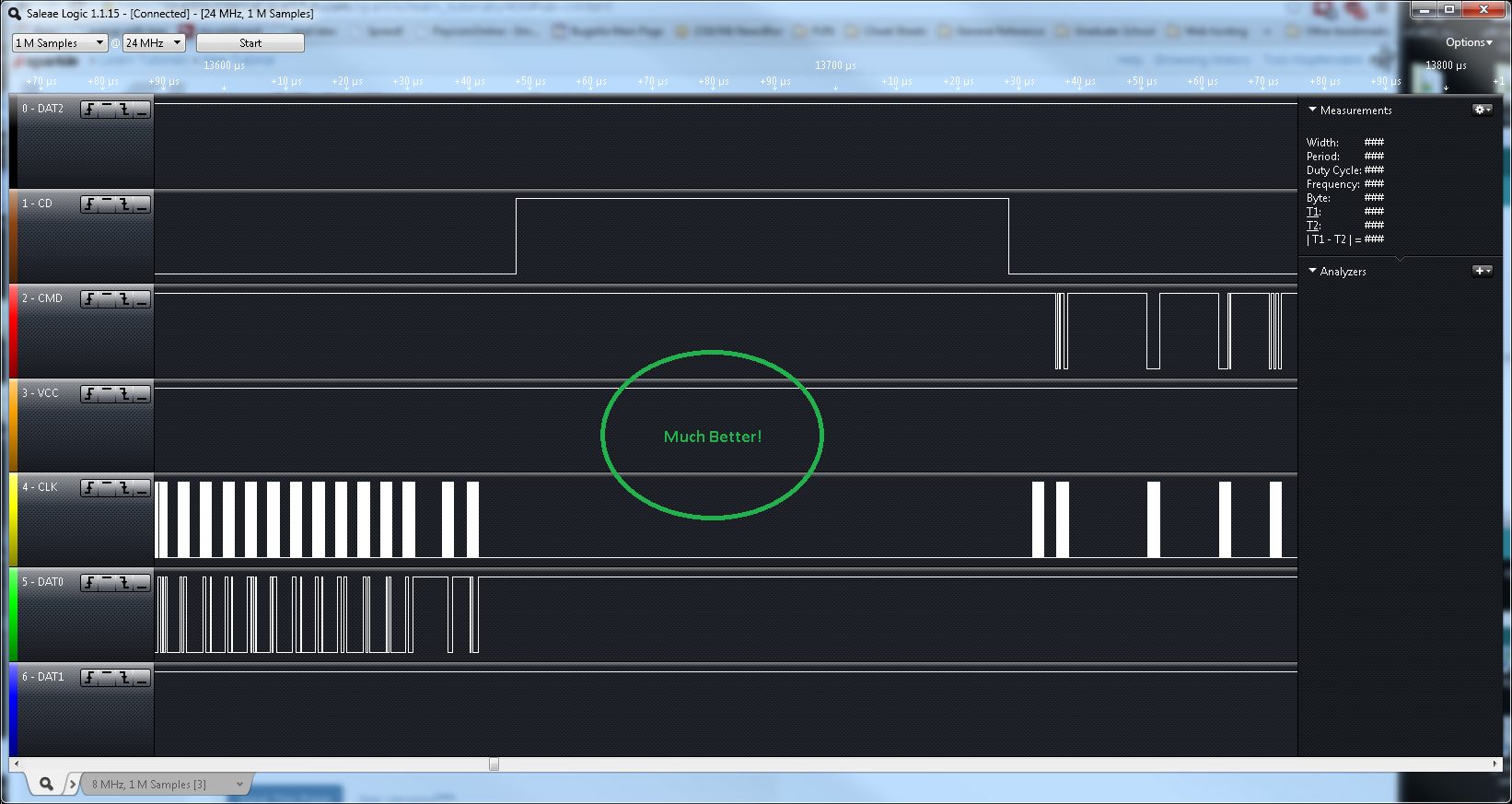
Again, this is a very simplified example, but you could use the Sniffer to verify the clock signal to your card, or to see if there are actual data signals being sent to the microSD card.