micro:bit Breakout Board Hookup Guide
 Shawn Hymel, Ell C
Hardware Overview
The micro:bit Breakout board allows you to utilize all of the pins on the micro:bit and opens up some previously inaccessible communication ports, like I2C and SPI.
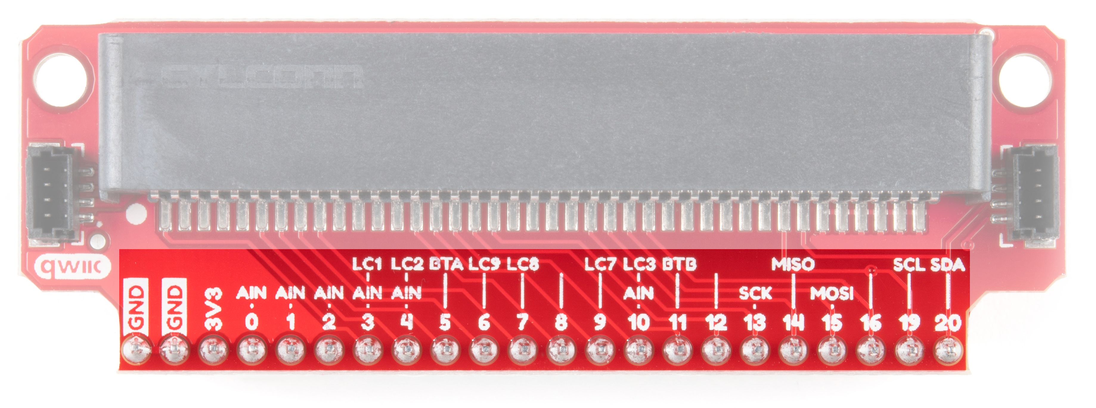
Pins
Most of the micro:bit's pins can be configured for one or more functions.
| Pin | Function 1 | Function 2 | Description |
|---|---|---|---|
| GND | Ground | ||
| GND | Ground | ||
| 3V3 | 3.3V | ||
| 0 | Analog In | Connected to large pin 0 | |
| 1 | Analog In | Connected to large pin 1 | |
| 2 | Analog In | Connected to large pin 2 | |
| 3 | Analog In | LED Column 1 | Controls part of LED array |
| 4 | Analog In | LED Column 2 | Controls part of LED array |
| 5 | Button A | Connected to Button A on micro:bit | |
| 6 | LED Column 9 | Controls part of LED array | |
| 7 | LED Column 8 | Controls part of LED array | |
| 8 | Open GPIO pin | ||
| 9 | LED Column 7 | Controls part of LED array | |
| 10 | Analog In | LED Column 3 | Controls part of LED array |
| 11 | Button B | Connected to Button B on micro:bit | |
| 12 | Open GPIO pin | ||
| 13 | SCK | GPIO or SPI clock | |
| 14 | MISO | GPIO or SPI MISO | |
| 15 | MOSI | GPIO or SPI MOSI | |
| 16 | Open GPIO pin | ||
| 19 | SCL | GPIO or I2 clock | |
| 20 | SDA | GPIO or I2 data |
Power Pin
The pin listed as 3V3 can be used as an input (regulated 3.3V, do not exceed 3.6V!) or an output if you plug a battery pack or USB into the micro:bit.
LCn Pins
The pins labeled with LCn (e.g. LC1, LC8) refer to pins that are used to control the LED array on the front of the micro:bit. You can use them as GPIO, but you'll often get weird patterns to show up on the LEDs, or when you write to the LED array, you may see unexpected behavior. If you use them as GPIO, we recommend disabling the LED display.
Qwiic Connectors
We've added a couple of Qwiic connectors on either side of the breakout board to take advantage of the I2C bus. For more information on the qwiic system, head on over to the Qwiic Connect System Landing Page.

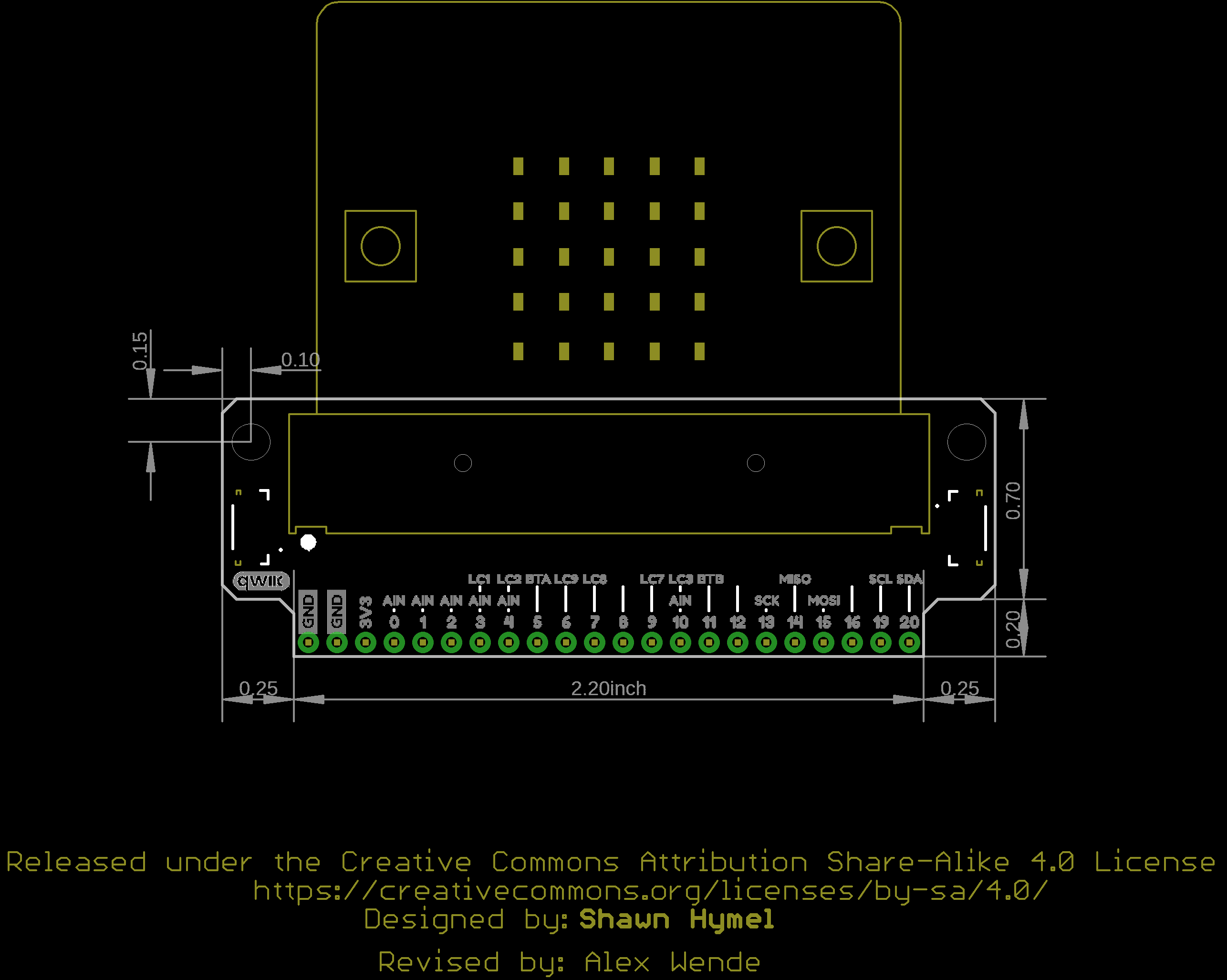
Board Outline