MAX31855K Thermocouple Breakout Hookup Guide
 .Brent.
Reading the Temperature
Installing the Library
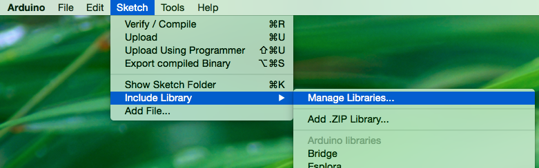
The library for this product is written to be compatible with Arduino IDE versions 1.5 and greater (1.6.x). The Arduino SPI library has changed in these versions, and our library relies on the more recent version. Since you are required to be running a recent version of the IDE we can use the handy new Library Manager feature. It is found in the 'Sketch' menu under 'Include Library', 'Manage Libraries...'
When you open the Library Manager you will find a large list of libraries ready for one-click install. To find the library for this product, search for 'k type' or 'digitizer', and the library you want will likely be the only option. Click on that library, and the 'Install' button will appear. Click that button, and the library should install automatically. When installation finishes, close the Library Manager.

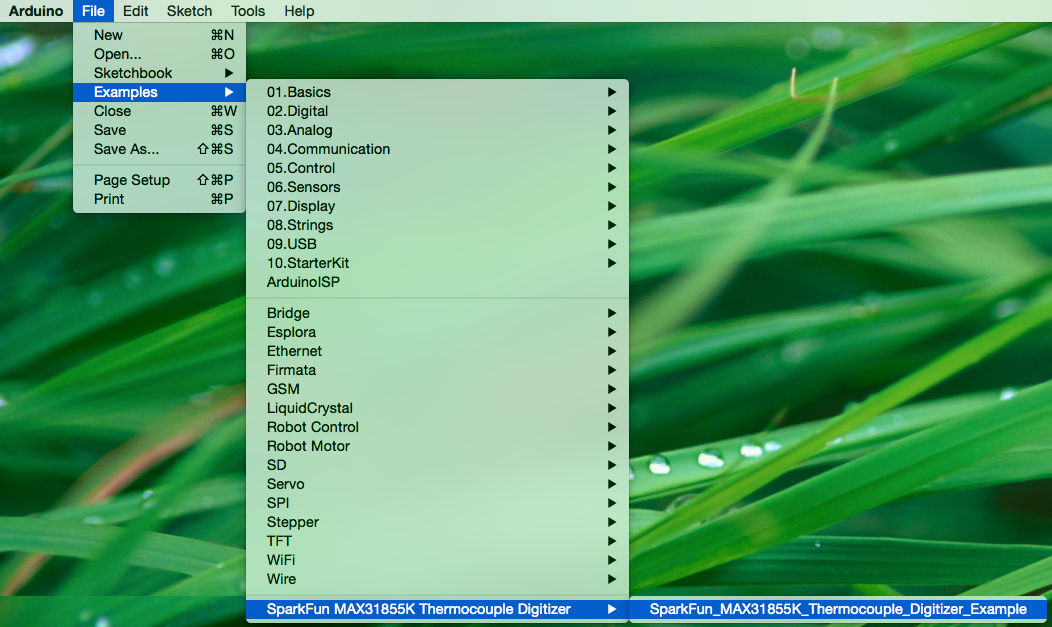
Now that the library is installed, an example sketch can be found in the 'Examples' submenu. Open this example.
language:cplusplus
/**************** MAX31855K_Thermocouple_Digitizer_Example.ino *****************
 *                                                                             *
 * MAX31855K Thermocouple Breakout Example Code                                *
 * brent@sparkfun.com                                                          *
 * March 26th 2015                                                             *
 * https://github.com/sparkfun/MAX31855K_Thermocouple_Digitizer                *
 *                                                                             *
 * Use the "serial monitor" window to read a temperature sensor.               *
 *                                                                             *
 * Circuit:                                                                    *
 * MAX31855K breakout attached to the following pins                           *
 *  SS:   pin 10                                                               *
 *  MOSI: pin 11 (NC)                                                          *
 *  MISO: pin 12                                                               *
 *  SCK:  pin 13                                                               *
 *  VCC:  pin 14                                                               *
 *  GND:  pin 15                                                               *
 *                                                                             *
 *                                                                             *
 * Development environment specifics:                                          *
 * 1.6.4                                                                       *
 * Arduino Pro Mini 328 3.3V/8MHz                                              *
 *                                                                             *
 * This code is beerware; if you see me (or any other SparkFun employee) at    *
 * the local, and you've found our code helpful, please buy us a round!        *
 * Distributed as-is; no warranty is given.                                    *
 ******************************************************************************/

#include <SparkFunMAX31855k.h> // Using the max31855k driver
#include <SPI.h>  // Included here too due Arduino IDE; Used in above header

// Define SPI Arduino pin numbers (Arduino Pro Mini)
const uint8_t CHIP_SELECT_PIN = 10; // Using standard CS line (SS)
// SCK & MISO are defined by Arduiino
const uint8_t VCC = 14; // Powering board straight from Arduino Pro Mini
const uint8_t GND = 15;

// Instantiate an instance of the SparkFunMAX31855k class
SparkFunMAX31855k probe(CHIP_SELECT_PIN, VCC, GND);

void setup() {
  Serial.begin(9600);
  Serial.println("\nBeginning...");
  delay(50);  // Let IC stabilize or first readings will be garbage
}

void loop() {
  float temperature = probe.readCJT();

  // Read methods return NAN if they don't have a valid value to return.
  // The following conditionals only print the value if it's not NAN.
  if (!isnan(temperature)) {
    Serial.print("CJT is (˚C): ");
    Serial.println(temperature);
  }

  // Read the temperature in Celsius
  temperature = probe.readTempC();
  if (!isnan(temperature)) {
    Serial.print("Temp[C]=");
    Serial.print(temperature);
  }

  // Read the temperature in Fahrenheit
  temperature = probe.readTempF();
  if (!isnan(temperature)) {
    Serial.print("\tTemp[F]=");
    Serial.print(temperature);
  }

  // Read the temperature in Kelvin
  temperature = probe.readTempK();
  if (!isnan(temperature)) {
    Serial.print("\tTemp[K]=");
    Serial.print(temperature);
  }

  // Read the temperature in Rankine
  temperature = probe.readTempR();
  if (!isnan(temperature)) {
    Serial.print("\tTemp[R]=");
    Serial.println(temperature);
  }

  delay(750);
}
Code To Note
language:cplusplus
// Define SPI Arduino pin numbers (Arduino Pro Mini)
const uint8_t CHIP_SELECT_PIN = 10; // Using standard CS line (SS)
// SCK & MISO are defined by Arduiino
const uint8_t VCC = 14; // Powering board straight from Arduino Pro Mini
const uint8_t GND = 15;
This block of code, found above the setup function in the main sketch, is where you will configure the pins used to communicate with the MAX31855K breakout. If you are using another board, or another power supply, you will want to edit these!
Serial.begin(9600);
Before using the serial monitor, you must call Serial.begin() to initialize it. 9600 is the "baud rate", or communications speed. When two devices are communicating with each other, both must be set to the same speed.
float temperature = probe.readCJT();
All of the temperature reading functions return floating point values. Floating point numbers are any number that isn't a whole integer number. '1' is and integer, while '1.01' is a floating point number. One special floating point number is NaN, or Not a Number. It represents things that aren't real numbers such as 0/0 (divide by zero is 'undefined'). If a temperature reading function returns NAN it means that a real temperature wasn't read, and it's time to check your hardware.
Running The Code
At this point the hardware should be correctly connected, the library should be installed, and the example sketch should be opened. Select the correct serial port in the 'Port' submenu of the 'Tools' menu. Click the 'Upload' button, or sleect 'Upload' in the 'Sketch' menu. The code should compile and be uploaded to the Arduino. Once the code upload finishes verifying, open the serial monitor (found in the 'Tools' menu).
What You Should See
You should be able to read the temperature your thermocouple is detecting on the serial monitor in the Arduino IDE. If it isn't working, make sure you have assembled the circuit correctly and verified and uploaded the code to your board.
Example of what you should see in the Arduino IDE’s serial monitor:
language:cplusplus
Beginning...
CJT is (˚C): 25.94
Temp[C]=26.50   Temp[F]=79.70   Temp[K]=299.65  Temp[R]=539.37
...
...
...
Beginning... only prints once to mark the beginning of the code running. The next two lines show the Cold Junction Temperature (CJT), followed by the thermocouple measurement in a handful of common units. The CJT is the temperature of the breakout board, and the other temperature reading is that of the tip of your thermocouple. These two lines of temperature readings should be updated and reprinted every 3/4 of a second.
Troubleshooting
Nothing Seems to Happen
This program has no outward indication it is working. To see the results, you must open the Arduino IDE's serial monitor.
Gibberish is Displayed
This happens because the serial monitor is receiving data at a different speed than expected. To fix this, click the pull-down box that reads "*** baud" and change it to "9600 baud".
Temperature Value is Unchanging
Try pinching the sensor with your fingers to heat it up or pressing a bag of ice against it to cool it down. Boiling water should be about 100°C, while ice should be about 0°C.