MAX31855K Thermocouple Breakout Hookup Guide
 .Brent.
Hardware Hookup
Now, let's dive in and see how to connect the Thermocouple Breakout.
Solder/Wire Breakout
The first assembly step is creating a reliable, electrical connection from the breakout to your control board. You'll need to solder either headers or wires to your breakout boards, deciding if straight or right-angle headers or wire work best for you.
If you're going to stick the breakout board into a breadboard, other prototyping board, or an Arduino Pro Mini, straight male headers might be the best choice. You might want to solder some right angle headers to the short edge of the Pro Mini so it's easy to plugin the FTDI Basic.
Select a Power Source
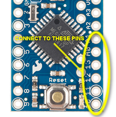
The MAX31855K requires from +3.0V to +3.6V (+3.0V nominal). Since the MAX31855K only draws 1.5 mA maximum, this tutorial will use D14 for power. This lets use line up all of the SPI and power pins on one compact row. One could also power the board from any similar power supply.
Connecting an Arduino
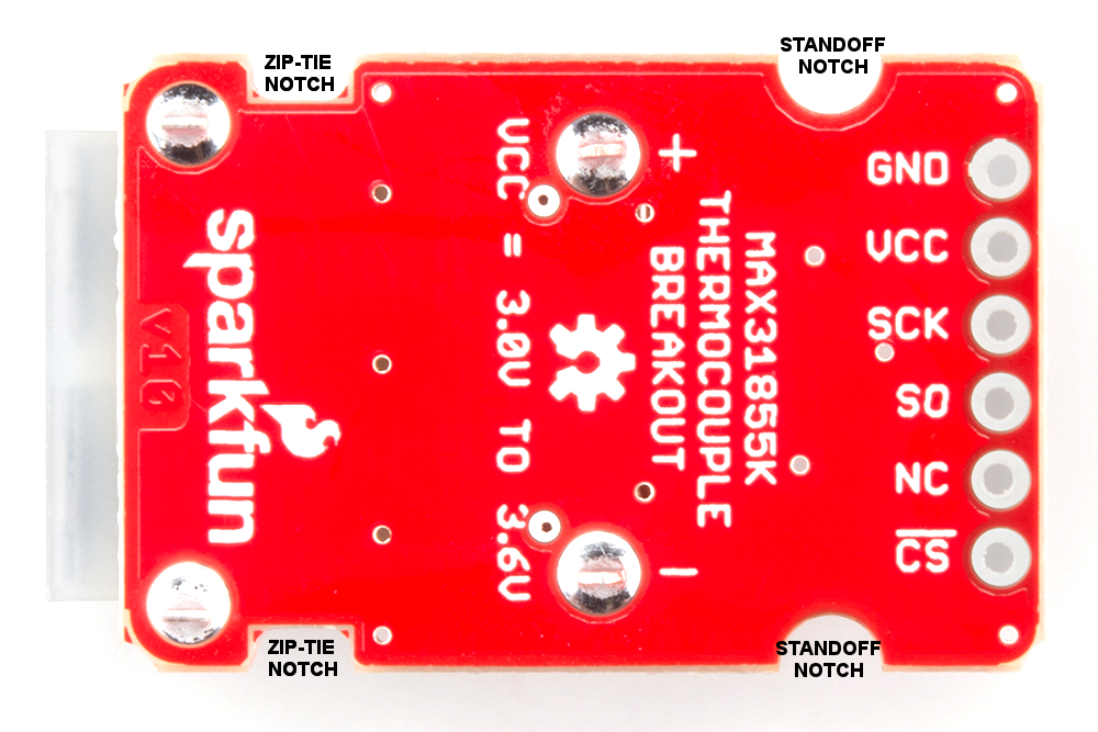
This hookup is fairly straightforward. We need so little power, we can connect the breakout to the sequential pins D10-A1. Since the MAX31855K is read-only, pin D11(MOSI) isn't connected on the breakout board & can be used for other functions such as SS for a second thermocouple board.Make your connections as follows:
| Thermocouple Breakout Pin | Arduino Pin | Function |
|---|---|---|
| GND | A1 | Ground |
| VCC | A0 | Digital pin set to 3.3V in |
| SCK | D13 | Clock |
| SO | D12 | Serial Data Out |
| NC | NC (D11) | No Connect (can float on D11 for easy hookup) |
| CS | D10 | Chip Select |
Connecting a Type K Thermocouple
As covered in the previous section, potentials are formed due to a temperature gradient between junctions of dissimilar metals. We want to minimize the number of these junctions ideally down to two: the hot at the end of the thermocouple, and the cold at the MAX31855K. Every connection in addition to these can skew the reading. The breakout board is designed to accept a standard thermocouple connector, for convenience and compatibility with probes you may already own. These connectors aren't necessary, and you could solder a thermocouple directly into the through holes labeled '+' and '-'.
If you decide to solder the thermocouple directly to the breakout board, it is recommended that the thermocouple be mounted for strain relief to avoid breaking the thin wires. Notches have been provided in the PCB opposite the header for this purpose. One could wrap the thermocouple around this part of the board and squirt on some hot glue, or a zip-tie can be wrapped around the notches to hold the thermocouple. These zip-tie notches can also be used to attach the board to your project.

If you opted for the connector, your circuit will look more like this:
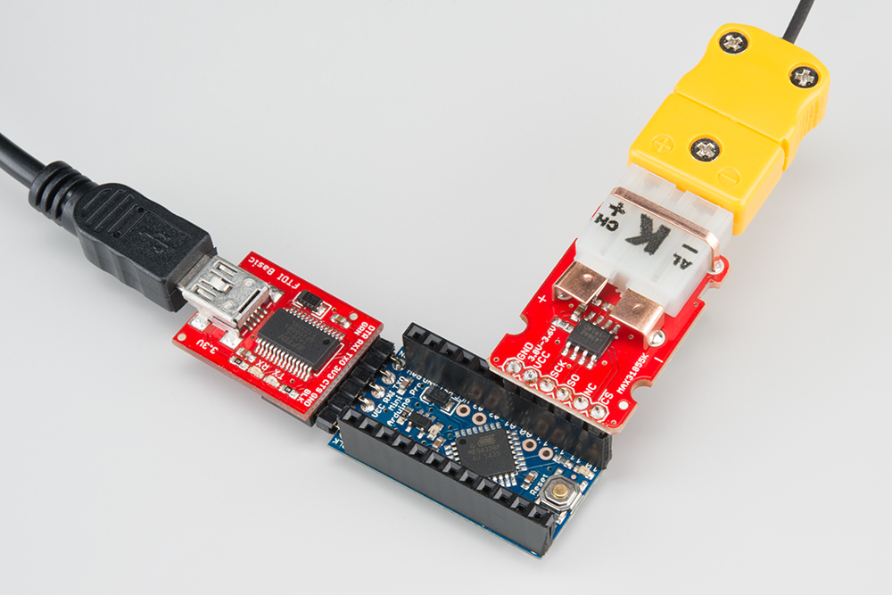
For ease of use in this particular application, I chose to solder female headers to all holes on the top of the Arduino. I also soldered a male header to the bottom of the breakout board.
Mounting Options
There is no need to mount the breakout board, but we have provided several ways to make it easy. Hot-glue and double-sided foam tape work, as always. We also provided notches for zip-ties. Grab a zip-tie, loop it around the PCB and any object, and pull it tight. There are also notched out holes for our standard standoffs and screws. find or make two holes 20 mm apart, center-to-center, and screw the board down. These same notches can also be used for a zip-tie, some conductive thread, or let your imagination go wild!