Making Music with the FreeSoC2
 Nick Poole
PSoC Schematic
Now that the FreeSoC board is wired up, let's open up the PSoC Creator software and take a look at the project. You can get the project files from the GitHub Repo here. When you open up the schematic view, you'll see the whole project at once:
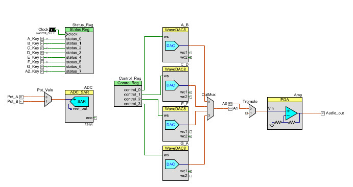
As you can see, it's split up into a few discrete modules with inputs on the left and outputs on the right. The easiest way to understand what's happening here is to break it down by section:
Digital Inputs
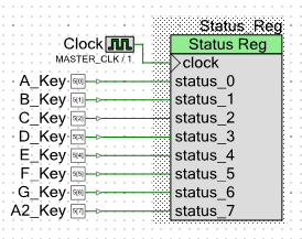
You'll remember from the hardware overview that we connected 8 pushbuttons to a row of analog pins on the FreeSoC board. In order to read the status of these buttons, we need to route them internally to something called a status register. The status register accumulates the status of up to 8 digital pins and allows you to fetch them using simple function calls in the firmware. Every time we call Status_Reg.Read() it will return an 8-bit number that represents whether each pin is high or low.
Analog Inputs
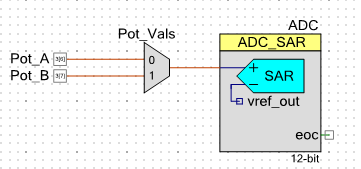
To read the potentiometers, we'll need to set up an ADC. If you're familiar with the ADC on the Arduino, the SAR on the FreeSoC is very similar. There aren't enough separate ADCs to set up one for each analog input, which would be a waste of resources anyway, so we need to multiplex the input. The component labeled Pot_Vals is a 2-channel analog multiplexer that allows us to connect either of the two potentiometers to the ADC. To get a reading from a specific potentiometer, the first thing we need to do is call Pot_Vals_Select() to connect the right pin to the ADC. Then we start the ADC conversion and finally retrieve the ADC result.
Signal Generator and Output
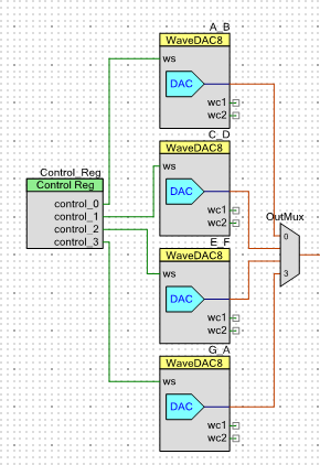
This is the heart of the project, and it's based on an awesome component called the WaveDAC. The WaveDAC combines a waveform generator with a digital-to-analog converter so that all you need to do in order to make an analog waveform is define the waveshape and the frequency. Each WaveDAC can store two predefined waveshapes that can be selected during runtime by switching the digital input labeled ws.
Because each WaveDAC will only store two waveforms, we need to stack a few of them to get 8 distinct tones. Also, because they're constantly generating a tone we need a way of switching between the WaveDACs so the outputs are piped into a multiplexer.
Finally, the WaveDAC ws lines are all tied to a control register. A control register is similar the status register except that it works as an output instead of an input. By making simple function calls in the firmware, we can control a number of digital signals during runtime.
Gain and Tremolo
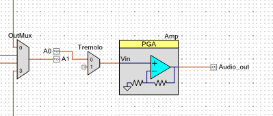
The last two stages before the final output are the tremolo, which is simply a multiplexer with one input left floating, and the variable gain, which is achieved using a programmable gain amplifier.
You'll notice that the output from the signal generator stage doesn't go directly into the Tremolo multiplexer. This is because PSoC Creator doesn't allow you to connect the output of one multiplexer to the input of another. We got around this by bridging two analog pins together and sending the signal through.
The tremolo effect is achieved by switching the multiplexer back and forth between two channels, one is connected to the output of the signal generator stage and one is left unconnected. By controlling the delay between channels, we can control the rate of the tremolo.
The gain control is achieved by sending the output from the tremolo stage into a Programmable Gain Amplifier or PGA. The PGA amplifies the incoming signal by a factor set during runtime by the firmware.
To find out how all of this works together, we'll need to tuck into the firmware...