Lumenati Hookup Guide
Hardware Overview
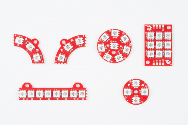
There are six different variations of Lumenati boards.
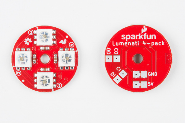
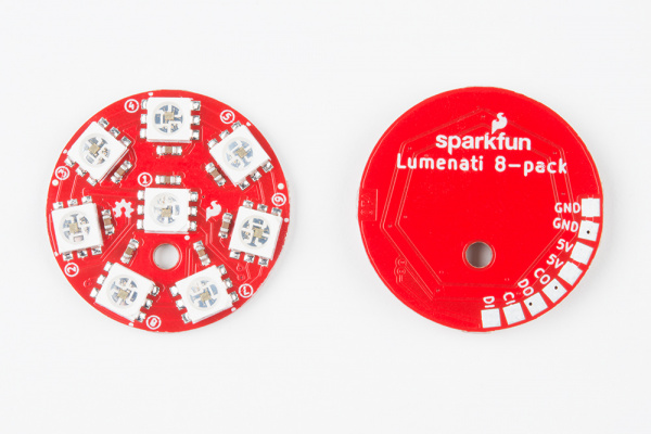
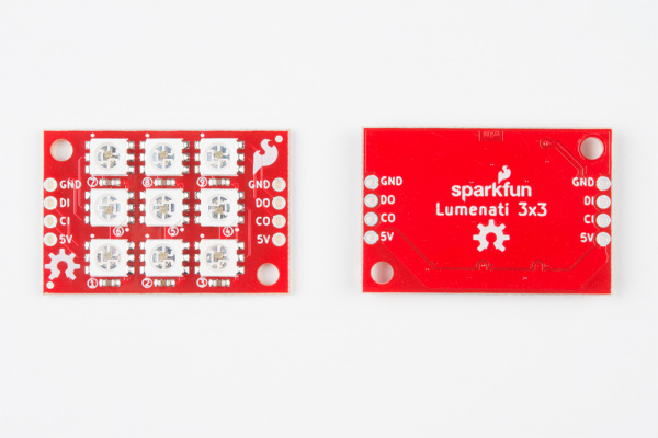
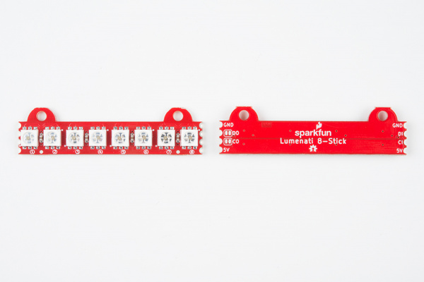
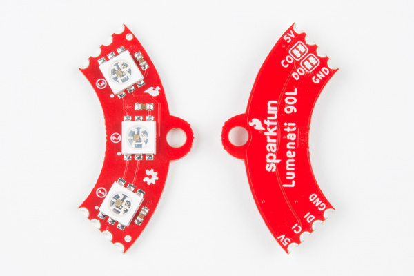
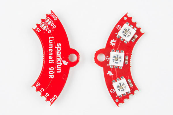
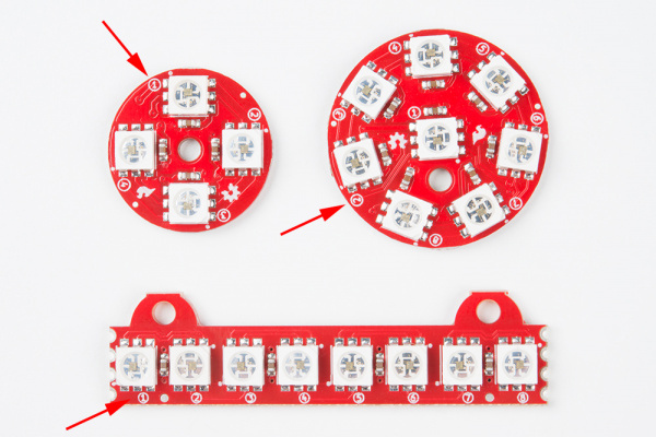
Each of the Lumenati boards are shown below:
Daisy-chaining Lumentai Boards
Any of the boards can be used stand-alone or daisy-chained. However, the 8-stick, 90L and 90R were designed with easy daisy-chaining specifically in mind.
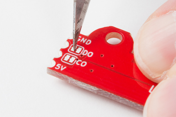
There are also solder jumpers on the CO and DO (clock out and data out) of these 3 boards. Those are there so that you can interrupt those signals in case you make a closed-loop design where you don't want the clock and data from your last LED to interfere with the clock and data to your first. +5V and ground traces are left to be contiguous in such cases to maximize current throughput. The solder jumpers on CO and DO come closed with a small trace bridging the solder pads. If you wish to open them, just take a small hobby knife (or similar implement of destruction) and carefully cut out that trace.
The APA102C addressable LEDs that are used on the Lumenati boards operate on +5V power input, as well as 0-5V logic levels for clock and data. The data interface is basically an SPI-like, with the exception that there is no data available coming back from the LEDs (no MISO line). Trace widths for +5V and ground have been maximized for better current through-put for long led chains.
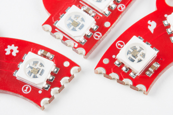
Additionally, LEDs on each board are labeled with numbers indicating their position in the sequence to help you design code more easily.
As mentioned earlier, each APA102C is capable of drawing close to 60mA when it's fully on. Care should be taken to keep that in mind when designing long LED chains. Figure out what your worst-case current draw could be, and plan accordingly!
