Lumenati Hookup Guide
 Pete-O
Example Using a Raspberry Pi 3
For this example, we'll be using a Raspberry Pi 3, a PCA9306 Level Translator Breakout, a 5V power supply and the Lumenati boards that we put together in the last section. The hookup will look like this:
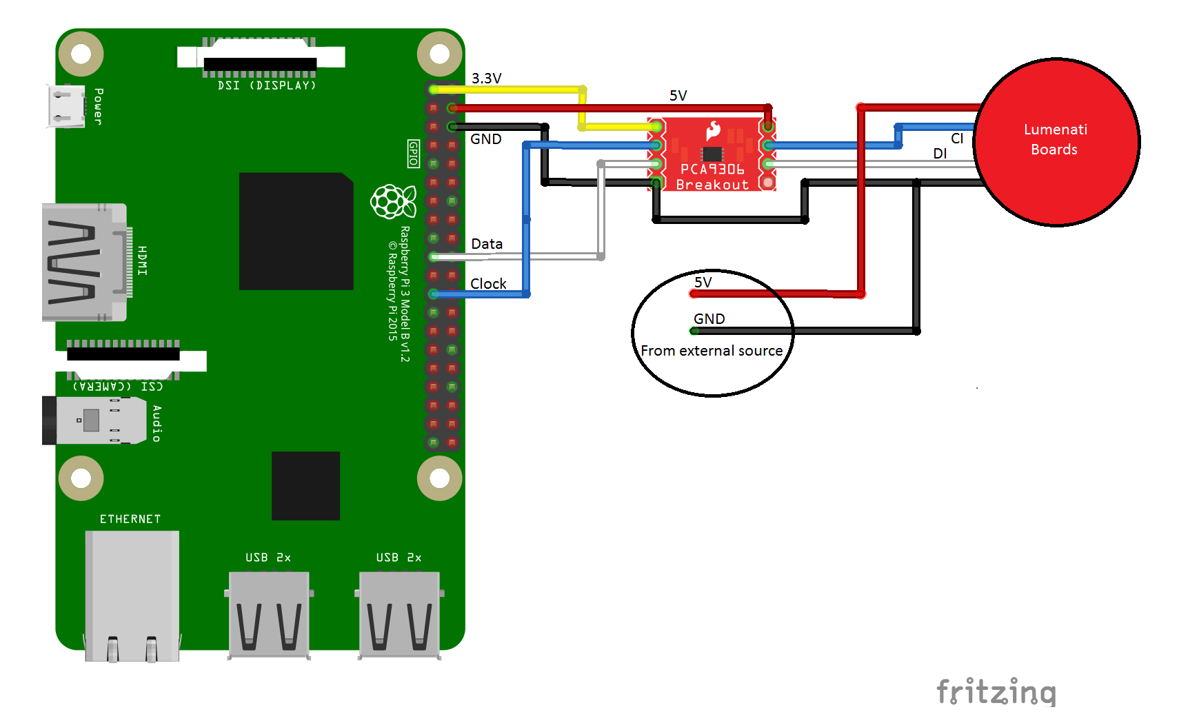
You'll notice from the diagram that the Lumenati boards are powered directly from an external 5V power supply and not from the header on the Raspberry Pi. While it is possible to drive the circuit as constructed with the supplied demo code from the Pi header, the 5V that's available there is fused. Since it is difficult to predict how much current the Pi itself is going to draw at any given moment, driving the LEDs through the Pi as well can become problematic with increased LED count and increased brightness, risking a brown-out condition with increased current consumption. Circumvent that condition entirely by tapping 5V and ground on the power supply before it reaches the Pi.
The connections of interest are in the following table.
| RasPi Pin # | Description | Goes to PCA9306 Pin |
|---|---|---|
| 1 | 3.3V (for low-side level shifting reference) | VREF1 |
| 4 | 5V (for high-side level shifting reference) | VREF2 |
| 6 | GND (ground for level shifting reference) | GND |
| 19 | Data | SCL1 |
| 23 | Clock | SDA1 |
Astute readers will notice that we've connected a clock signal to what looks like a data channel and a data signal to what looks like a clock channel on the PCA9306, if the labels are to be believed. But here's a little secret about those channels: they're virtually identical, electrically speaking. While the labels may be incongruent, it made the wiring just slightly more uniform.
The connections from the PCA9306 Breakout to the Lumenati boards are thus:
| PCA9306 Pin | Description | Lumenati Pin |
|---|---|---|
| SDA2 | Clock | CI |
| SCL2 | Data | DI |
| GND | GND (ground for level shifting reference) | GND |
We've put together some really simple python code for you to get started with. The first is a really simple library to set up an array with the LED parameters and write them to the Lumenati boards.
language:python
#Set up the SPI port on the Pi
import spidev
spi = spidev.SpiDev()
spi.open(0,0)

#Create LED array by sending this function num_LEDs
def set_LED_quantity(num_LEDs):
    global NUM_LEDs
    NUM_LEDs = num_LEDs
    global LED_array
    LED_array = [[0,0,0,0]] * NUM_LEDs

#Puts LED(num) parameters into LED_array
#Red, Green and Blue (r,g,b) values must be between
#0-255. Brightness must be between 0 and 31.
def set_LED(num, r, g, b, brightness):
    if (brightness > 31) | (brightness < 0):
        brightness = 15
    if (r > 255) | (r < 0):
        r = 100
    if (g > 255) | (g < 0):
        g = 100
    if (b > 255) | (b < 0):
        b = 100

    LED_array[num] = [r, g, b, brightness | 0xE0]

#These 4 bytes have to be written at the start and
#end of each data frame when writing to the LEDs
def _start_end_frame():
    for x in range (4):
            spi.xfer2([0x00])

#Write data to the LEDs
def WriteLEDs():
    _start_end_frame()
    for LED in LED_array:
        r, g, b, brightness = LED
        spi.xfer2([brightness])
        spi.xfer2([b])
        spi.xfer2([g])
        spi.xfer2([r])

    _start_end_frame()
The second demonstrates the use of those functions and makes some pretty lights.
language:python
#This is demonstration code for the Lumenati line of APA102c boards,
#specifically using (4) 90L boards surrounding one 8-pack board.

import time

from SFE_Lumenati import set_LED_quantity, WriteLEDs, set_LED

#Set up array, 20 LEDs
set_LED_quantity(20)

#Delay duration
wait = 0.15

#Global brightness
brightness = 15 #range is 0-31

try:
    while True:

        for y in range (5):

            #center, white
            set_LED(0,25,25,25,brightness)

            #inner ring, red
            for x in range (7):
                set_LED(x+1,25,0,0,brightness)

            #outer ring, white
            for x in range (12):
                set_LED(x+8,25,25,25,brightness)

            #Write to the LEDs and wait
            WriteLEDs()
            time.sleep(wait)

            #center, red
            set_LED(0,25,0,0,brightness)

            #inner ring, white
            for x in range (7):
                set_LED(x+1,25,25,25,brightness)

            #outer ring, red
            for x in range (12):
                set_LED(x+8,25,0,0,brightness)

            #Write to the LEDs and wait
            WriteLEDs()
            time.sleep(wait)

        for y in range (5):

            #center, yellow
            set_LED(0,25,25,0,brightness)

            #inner ring, blue
            for x in range (7):
                set_LED(x+1,0,0,25,brightness)

            #outer ring, yellow
            for x in range (12):
                set_LED(x+8,25,25,0,brightness)

            #Write to the LEDs and wait
            WriteLEDs()
            time.sleep(wait)

            #center, blue
            set_LED(0,0,0,25,brightness)

            #inner ring, yellow
            for x in range (7):
                set_LED(x+1,25,25,0,brightness)

            #outer ring, blue
            for x in range (12):
                set_LED(x+8,0,0,25,brightness)

            #Write to the LEDs and wait
            WriteLEDs()
            time.sleep(wait)

except KeyboardInterrupt:
    pass
Click here to get the code. Just drop the two files from SparkFun_Lumenati_Code/Firmware/RasPi into the same folder, and run Lumenati_Demo.py. If the stars align (and you've done everything right), the result should look as below.