LoRaSerial Hookup Guide
 Nate
Nate 
Hardware Overview
The LoRaSerial is a SAMD21 based assembly with a SX1276 LoRa radio with innovative firmware to make things as simple as possible.
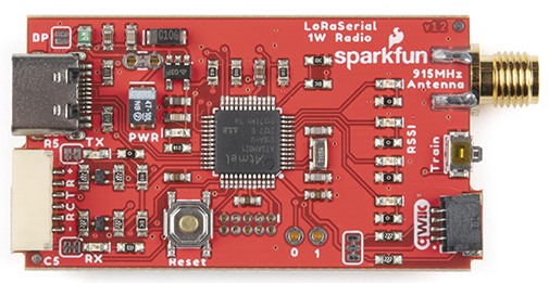
The LoRaSerial uses a 1W LoRa radio based on the SX1276 radio along with a SAMD21 utilizing the UF2 bootloader. Any serial received by the radio will be queued up, encrypted, and sent out. Any received packets are checked for CRC, Network ID, decrypted, then printed.
Note: By default there is a 50ms timeout in which the radio will wait for additional characters to be received until a partial frame is sent.
USB C
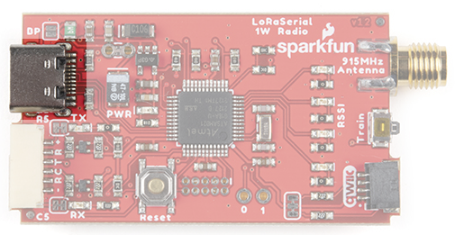
The USB C connector provides power and serial communication to the unit. LoRaSerial will automatically show up on a computer or SBC (single board computer) as a serial COM port at a default of 57600bps. Currently only 8-N-1 serial communication is supported but we are open to additional features as user’s needs arise.
6-Pin JST
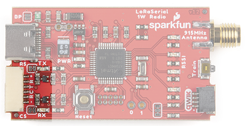
LoRaSerial features a ‘locking’ type 6-pin JST connector. The connector on LoRaSerial is X and mates with a connector JST-GHR-06V. Each LoRaSerial radio comes with a JST to breadboard friendly pins. If you need additional cables they are available here (Note: the wire color may be different between cables).
The pinout is as follows:
- PWR - 3.3-5V
- RX - Receive (Input into LoRaSerial)
- TX - Transmit (Output from LoRaSerial)
- CTS - Clear To Send (Input into LoRaSerial)
- RTS - Ready To Send (Output from LoRaSerial)
- GND - Ground
PWR (3.3-5V) - LoRaSerial requires 3.3 to 5V to operate. We recommend 5V for maximum transmission range but we’ve found operating off of a LiPo at 3.7 to 4.2V works great.
RX (Receive) - Connect this pin to the TX pin of your system. This pin is 3.3-5V tolerant and has an internal pull-up.
TX (Transmit - Connect this pin to the RX pin of your system. This pin uses 3.3V logic.
CTS (Clear To Send - (Optional) Connect this pin to a GPIO of your system. This pin is 3.3-5V tolerant and has an internal pull-up. When this pin is high the radio will continue to send data. If the host system pulls this pin low, the radio will stop sending data.
RTS (Ready To Send) - (Optional) Connect this pin to a GPIO of your system. This pin uses 3.3V logic. If the radio’s buffer (size currently is 4096 bytes) becomes full the system will drive RTS low indicating that it should not be passed more data. If more serial data is received, the buffer will be overwritten, oldest data first.
GND (Ground) - Connect this pin to the ground of your system.
RSSI LEDs
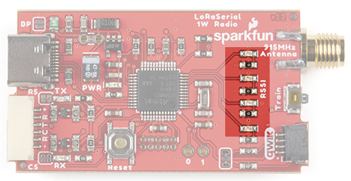
There are four LEDs indicating in real-time the received signal strength or RSSI. These LEDs are meant to indicate a qualitative level of receive strength. Don’t worry if you’ve got three LEDs rather than four. LoRa technology is capable of transmitting a long range in harsh RF conditions. As long as you’ve got one LED, you will be able to send and receive data.
RPSMA Connector
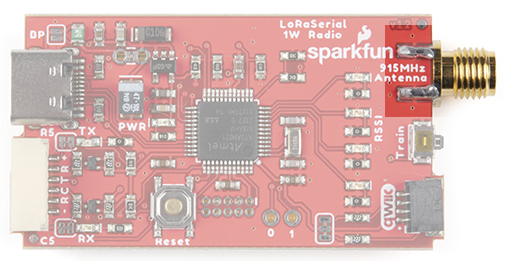
Attach a 915MHz RPSMA antenna to this port. Not sure which is SMA and which is RPSMA? Checkout this RF Connector Guide. The LoRaSerial is also compatible with large, LoRa type antennas. We recommend a good thick RG58 RPSMA extension from the radio to your antenna to minimize loss. Remember, we are transmitting at 1W so keep your cables and connectors to a minimum.
Qwiic Connector
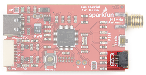
The Qwiic connector and I2C accessibility is not yet implemented.
Train Button
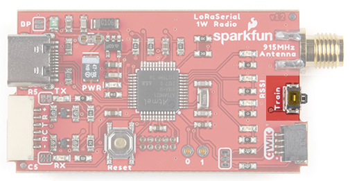
LoRa Serial uses a unique and very easy to use train feature. Each radio has a default Network ID and AES key programmed into it. Changing these keys is as easy as pressing a button!
Using a ball point pen or other small pointed device, press and hold the Train button for 2 seconds, until you see the RSSI LEDs begin to blink. You can release the button. If the LEDs begin to cylon (bounce back and forth) the device has entered training ‘wait’ mode where it waits for another device to ping it.
On the second radio, press and hold the Train button for 2 seconds, until you see the RSSI LEDs begin to blink. Release the button. The RSSI LEDs on both units will blink in unison indicating that the units are now trained to each other.
For security reasons the radios are both set to the lowest transmission power to minimize any eavesdropper from monitoring the transaction. While the ‘new’ keys are themselves encrypted, they are encrypted using the default AES key so one could theoretically back out the new AES keys if they are within ~30ft of the devices when the radios are being trained. If you’re paranoid, train the radios with the antennas off, within a few inches of each other. If total security is a concern, or if the radios cannot be physically brought near one another, the AES keys and/or the network IDs can be set via software commands.
Internal Reset Button
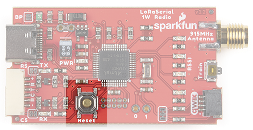
The firmware on the LoRaSerial can be upgraded from a computer without ever having to open the unit. In the rare case that the SAMD21 needs to be forced into bootloader mode the reset button should be quickly double tapped. The unit will then enter bootloader mode and wait for new firmware or for a reset event (button is pressed or power is cycled).
GPIO
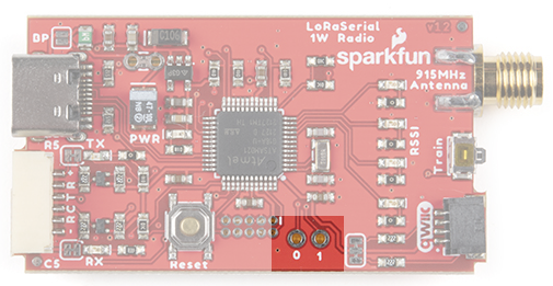
Two GPIOs capable of ADC are broken out for potential future use.
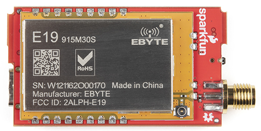
UFL Connector
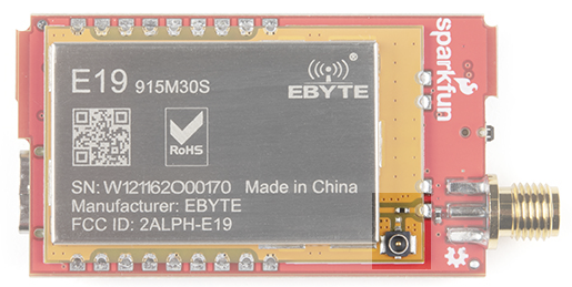
For advanced users, the 915/868MHz modules feature a U.FL connector. This can be helpful if you need to embed the radio in an enclosure and need an external bulkhead RP-SMA connector. To use the U.FL connection, desolder the 0402 0Ω jumper and move it to the U.FL's RF path.