LoRaSerial Hookup Guide
 Nate
Nate 
AT Commands
LoRaSerial radios are very flexible. By default the radio is looking for serial communication at 57600bps. Open the terminal of your choice and enter +++ and wait for an OK. The radio is now ready for an AT command.
Below is a brief list of commands:
| AT Command | Command Description |
|---|---|
| +++ | Enter command mode |
| AT | Reports OK |
| ATI | Show board variant, firmware |
| ATI0 | Show all user settable parameters |
| ATI1 | Show board variant |
| ATI2 | Show firmware version |
| ATI3 | Display latest RSSI |
| ATI4 | Generate random byte based on RSSI |
| ATI5 | Show max possible bytes per second |
| ATI6 | Show AES Key Values |
| ATI7 | Show FHSS Channel |
| RTI? | Show equivalent remote setting |
| ATO | Exit command mode |
| ATZ | Reboot the radio |
| AT&W | Write current parameters to EEPROM |
| AT&F | Reset all parameters to factory defaults |
| AT&T=RSSI | Show RX packet RSSI, SNR, and FreqError |
| ATT | Enter Training Mode |
| ATF | Enter Training Mode with Defaults |
| ATSn? | Display a parameter |
| ATSn=X | Set a parameter |
| RTSn? | Display remote parameter |
| RTSn=X | Set remote parameter |
For a PDF of the AT commands, click here.
The main user settable parameters are listed below and available here in PDF format. A parameter is set using the ATSx command. For example sending ‘ATS21=1’ will enable debug printing. This setting can be stored in NVM (non-volatile memory) by sending the ‘AT&W’ command.
Remote configuration is supported. If two radios are linked, all AT commands can be sent to the remote radio using the RT equivalent (ie, RTZ will reboot the remote radio). Be careful as it is very possible to break the link. For example, setting the remote AES key should be done first before setting the local AES key.
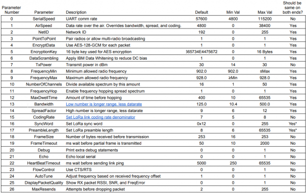
The table of common parameters is available here in PDF format.
SerialSpeed - Controls the baud rate in bits-per-second used over the UART connector. Data sent over USB will be sent/received regardless of this setting. Default is 57600bps. Allowed values are 2400, 4800, 9600, 14400, 19200, 38400, 57600, and 115200bps.
AirSpeed - This is the effective rate in bits-per-second at which data is sent over the air. In general, the lower the air speed, the greater the transmission distance. LoRaSerial uses large 4,000 byte buffers to receive and send serial over USB or UART at the SerialSpeed and begins sending that data in chunks over the air at the AirSpeed. The AirSpeed setting does not have to match the SerialSpeed. It is recommended to limit the total incoming data to match the AirSpeed. For example, regularly sending a group of 300 bytes with an air speed of 4800 bps (480 bytes per second) will allow the radio sufficient bandwidth. Sending 1,000 bytes per second with an air speed of 4800 bps (480 bytes per second) will within a few seconds overwhelm the link leading to buffer overflow and data loss. Default is 4800bps. Allowed values are 0, 40, 150, 400, 1200, 2400, 4800, 9600, 19200, 28800, and 38400 bits per second. 0 is a special value that allows the Bandwidth, SpreadFactor, and CodingRate settings to be used instead.
NetID - In PointToPoint mode each radio is paired with another radio. They will have unique frequencies that they will use. However, crosstalk is always possible. If a packet is received with a non-matching NetID it is discarded. Changing the NetID is a handy way to make sure your radio pair does not interfere with another pair of radios in the same vicinity.
PointToPoint - In point to point mode, two radios pass packets and acknowledge (confirm) the receipt of a given packet. Lost packets are automatically retransmitted up to MaxRends number of tries. When PointToPoint is turned off, acknowledgements are turned off. Any radio using the same settings will be able to receive packets from each other. This is most useful when you have one ‘base’ transmitter with multiple ‘rovers’ receiving that data.
EncryptData - By default all packets are encrypted using 128 bit AES GCM. Disabling this will not get greater range or bandwidth. Disabling encryption will allow all packets to be seen in clear text via an SDR or other monitoring device.
EncryptionKey - This is the 16 byte key used for AES encryption. While this can be set via command, we recommend using the train feature as this is much faster and less error prone.
DataScrambling - Enabling data scrambling will send all packets through an IBM data whitening process. This removes long sets of 1s or 0s from the packet to reduce DC bias during transmission. This is generally not needed and is not recommended when AES encryption is enabled. By default scrambling is turned off.
TxPower - The LoRaSerial uses a high power 1W transceiver. By default, all transmissions are sent at the highest possible power of 30dBm which is compliant with FCC Part 15.247 when used with an antenna that has a gain of 6dBi or less. If your local regulations require lower transmission power this setting can be lowered. Allowed values are 30 down to 14dBm. Note: The chosen setting is the actual measured transmit power at the SMA connector. An internal lookup table sets the radio settings accordingly.
FrequencyMin/FrequencyMax - These are the lower and upper bounds for the allowed transmission frequencies in megahertz. By default this is 902.0 to 928.0.
NumberOfChannels - The available spectrum (default is 902MHz to 928MHz) is divided by this number of channels to create the channel spacing and allowed frequency list (aka the ‘hop table’). The default is 50 channels to meet FCC Part 15.247 compliance and may be changed to meet local regulations.
FrequencyHop - The LoRaSerial implements frequency hopping spread spectrum (FHSS) by default to meet FCC Part 15.247 compliance. Turning off frequency hopping is not recommended unless You Know What You’re Doing™.
MaxDwellTime - The number of milliseconds of transmission allowed on a given frequency before hopping intra-packet. The default is 400ms to be compliant with FCC Part 15.247. This means the radio will change its frequency to the next channel in the hop table during the packet transmission. Note this is the maximum dwell time; depending on the air speed setting the radio may have a hopping period that is shorter than the dwell time.
Bandwidth - The bandwidth used around a given frequency during LoRa transmissions. Setting is in kHz. This setting is overwritten if the AirSpeed setting is non-zero. It is recommended to use the air speed setting unless you are very aware of the consequences. Change AirSpeed to 0 to use a custom bandwidth. In general a lower bandwidth number provides longer range, but lower overall data rate. Allowed bandwidths: 10.4, 15.6, 20.8, 31.25, 41.7, 62.5, 125.0, 250.0, and 500.0kHz.
SpreadFactor - The spread factor used during LoRa transmissions. It is recommended to use the air speed setting unless you are very aware of the consequences. This setting is overwritten if the AirSpeed setting is non-zero. Change AirSpeed to 0 to use a custom spread factor. In general a higher spread factor provides longer range, but lower overall data rate. Allowed spread factors: 6 to 12 (inclusive).
CodingRate - The coding rate used during LoRa transmissions. It is recommended to use the air speed setting unless you are very aware of the consequences. This setting is overwritten if the AirSpeed setting is non-zero. Change AirSpeed to 0 to use a custom coding rate. In general a higher spread factor provides longer range, but lower overall data rate. Allowed spread factors: 6 to 12 (inclusive).
SyncWord - The byte used to synchronize LoRa transmissions. In general this is set to 0x12 for non-LoRaWAN networks. Note that two LoRa radios with the same settings but different sync words have been shown to intermittently receive packets from each other. Therefore, using a unique synch word does not guarantee exclusivity. Allowed values: 0 to 255.
PreambleLength - The number of sync words to send at the start of a packet. Note that two LoRa radios with the same settings but different preamble lengths have been shown to intermittently receive packets from each other. Therefore, using a unique preamble length does not guarantee exclusivity. Allowed values: 6 to 65535.
FrameSize - The number of bytes to be received before initiating a transmission. The default is 253. Allowed values: 16 to 253.
FrameTimeout - The number of milliseconds of timeout before a partial packet is sent. For example if a partial frame of 12 bytes are received, the radio will wait this amount for more bytes before initiating a transmission. The default is 50ms. Allowed values: 10 to 2000ms.
Debug - Enabling debug messages will print additional information about the radio’s state and packet information. Default is off.
Echo - By default the radio will not echo the incoming serial. This is helpful at times if a user is typing data directly into a terminal. During AT configuration echo is turned on regardless of this setting.
HeartBeatTimeout - When PointToPoint mode is enabled, a radio will send a ping packet every HeartBeatTimeout number of milliseconds if there is no data traffic. The default is 5000ms (5 seconds). Allowed values: 250 to 65535ms.
FlowControl - If flow control is enabled, the radio will not print data if CTS is low (host is telling the radio to hold its horses). If flow control is enabled, the radio will pull RTS low if its serial buffer is full (radio is telling the host to hold its horses). CTS and RTS pins are only exposed on the UART connector but apply to both USB and serial data streams. By default, flow control is turned off. Internal pullups are used so RTS and CTS can be left floating if not used.
AutoTune - Based on the frequency error of the last received packet, tune the receive frequency accordingly. Currently, this feature is not recommended. Default is off.
DisplayPacketQuality - Show RSSI (received signal strength indicator), SNR (signal to noise ratio), and FreqError (frequency error) for all received packets.
MaxResends - If PointToPoint is enabled, a radio will transmit a data packet and then wait for a response. If no response is received within 125% of the response packet’s air time, the data will be resent up to MaxResends. Default is 2. Allowed values: 0 to 255.