Lockitron Hardware Hookup Guide
This Tutorial is Retired!
This tutorial covers concepts or technologies that are no longer current. It's still here for you to read and enjoy, but may not be as useful as our newest tutorials.
 Shawn Hymel
Lockitron Overview
Before we connect the Lockitron to anything, we should take a look at its internals to get an idea of what it does. Remove the black, plastic cover, and take a look at the inside.
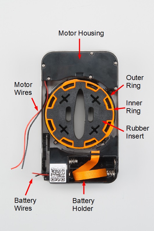
- Motor Housing - This section contains the motor and gears necessary for rotating the outer ring.
- Motor Wires - The + and - wires for controlling the motor.
- Outer Ring - This ring has teeth around the edges so it can be turned via the motor. It also contains a number of "bumps" that the 2 bottom limit switches can use to determine its position. Additionally, it holds the inner ring in place and allows it to freely spin 90º.
- Inner Ring - The inner ring can freely spin 90º within the outer ring. If the outer ring spins past this 90º stop, the inner ring will begin to spin with the outer ring (in either direction). This free spinning motion allows a user to manually lock and unlock the deadbolt.
- Rubber Insert - This piece fits over the deadbolt's thumbturn. It can be removed so that you can install the Lockitron on your door first before fitting the rubber insert onto the thumbturn.
- Battery Holder - A place to put 4x AA batteries and power the rest of the Lockitron (and possibly your electronics).
- Battery Wires - These wires (red for + and black for -) connect to the 4x AA batteries.
- It seemed to work best between 3 V and 9 V. It worked OK at 12 V, but judging by the fact that the Lockitron requires 4x AA batteries, 6 V is likely the optimal voltage.
- Just operating the rings (no deadbolt), the motor drew about 500 mA.
- The motor happily drew 3+ amps when stalled. Make sure your batteries or power supply can handle that if you accidentally get the rings stuck. The TB6612FNG motor driver can handle 1.2 A continuous and 3.2 A peak, so try not to let the motor stall for too long!
If you plan to wire up the limit switches (a good idea), now is a good time to remove the battery holder. Unscrew the two black Phillips screws from the bottom of the battery holder (underneath where the batteries would go), and carefully remove the holder.
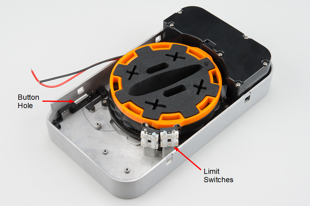
- Limit Switches - There are 4 limit switches that are pressed whenever one of the "bumps" on the rings moves by. The top 2 switches coincide with the "bumps" on the inner ring (orange), and the bottom 2 switches look for "bumps" on the outer ring (black).
- Button hole - On the original Lockitron, a button stuck out of this hole that allowed you to configure the Lockitron's wireless properties. Since we don't have the original electronics, we are going to use the hole to route wires out of the Lockitron housing.
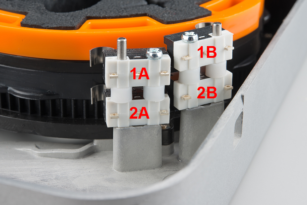
We are going to assign arbitrary names to the limit switches so that we know what to call them in our code. We also recommend labeling the wires (e.g. with a piece of tape and a pen) that are connected to the limit switches. When we put the battery housing back in the Lockitron, it will be very difficult to see which wire connects to which switch.
- 1A - First to be hit when the inner ring (orange) spins counterclockwise.
- 1B - First to be hit when the inner ring (orange) spins clockwise.
- 2A - First to be hit when the outer ring (black) spins counterclockwise.
- 2B - First to be hit when the outer ring (black) spins clockwise.