Lockitron Hardware Hookup Guide
This Tutorial is Retired!
This tutorial covers concepts or technologies that are no longer current. It's still here for you to read and enjoy, but may not be as useful as our newest tutorials.
 Shawn Hymel
Lock It up
The Lockitron Mechanical Assembly from SparkFun is a perfect solution for the DIY home automation or Internet of Things (IoT) enthusiast, whether you want to make your life easier by not awkwardly fumbling with keys or add some extra security in your home with three-factor authentication.
Lockitron, the company, offers a complete solution that includes the mechanical assembly, embedded electronics that can connect to the Internet via Wifi or your phone over Bluetooth, and apps to control your deadbolt. That is definitely the easy, done solution to your automated locking needs.
But, you're not here for easy, are you? What we have is the mechanical assembly, including motor and battery pack, to help you complete the automated security in your evil lair. An off-the-shelf solution just won't cut it.
Covered in This Tutorial
In this guide, we will go over the guts of the Lockitron assembly and show you how to connect it to an Arduino Pro Mini. The Pro Mini, by itself, has no wireless capabilities. How you ultimately control your Lockitron will be up to you, whether it's a tap sensor or through a WiFi connection.
Materials Used
In addition to the Lockitron Mechanical Assembly, you will need a few additional components:
Recommended Reading
Before getting started with the Lockitron, there are a few concepts that you should be familiar with. Consider reading some of these tutorials before continuing:
Lockitron Overview
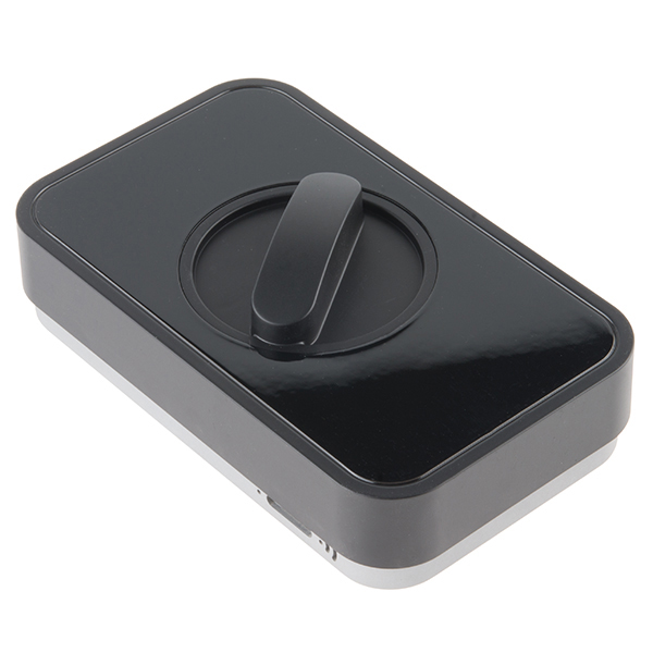
Before we connect the Lockitron to anything, we should take a look at its internals to get an idea of what it does. Remove the black, plastic cover, and take a look at the inside.
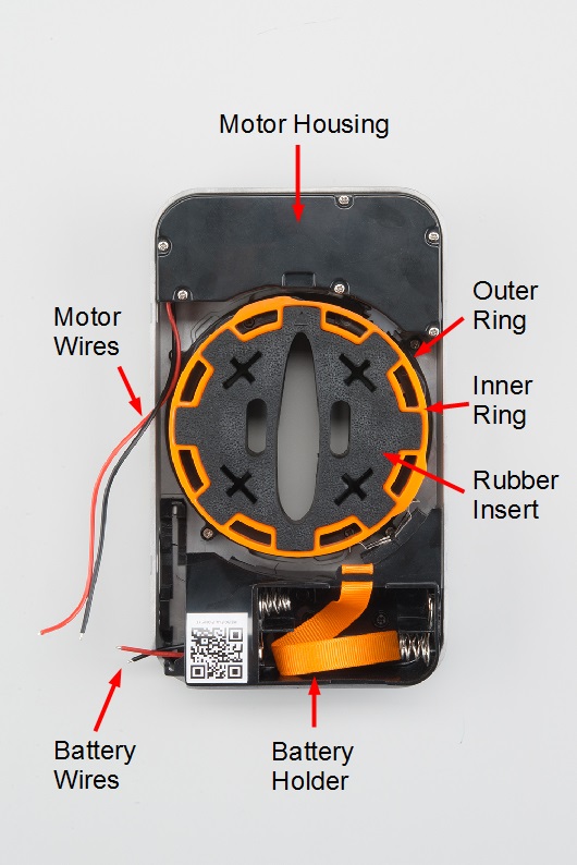
- Motor Housing - This section contains the motor and gears necessary for rotating the outer ring.
- Motor Wires - The + and - wires for controlling the motor.
- Outer Ring - This ring has teeth around the edges so it can be turned via the motor. It also contains a number of "bumps" that the 2 bottom limit switches can use to determine its position. Additionally, it holds the inner ring in place and allows it to freely spin 90º.
- Inner Ring - The inner ring can freely spin 90º within the outer ring. If the outer ring spins past this 90º stop, the inner ring will begin to spin with the outer ring (in either direction). This free spinning motion allows a user to manually lock and unlock the deadbolt.
- Rubber Insert - This piece fits over the deadbolt's thumbturn. It can be removed so that you can install the Lockitron on your door first before fitting the rubber insert onto the thumbturn.
- Battery Holder - A place to put 4x AA batteries and power the rest of the Lockitron (and possibly your electronics).
- Battery Wires - These wires (red for + and black for -) connect to the 4x AA batteries.
- It seemed to work best between 3 V and 9 V. It worked OK at 12 V, but judging by the fact that the Lockitron requires 4x AA batteries, 6 V is likely the optimal voltage.
- Just operating the rings (no deadbolt), the motor drew about 500 mA.
- The motor happily drew 3+ amps when stalled. Make sure your batteries or power supply can handle that if you accidentally get the rings stuck. The TB6612FNG motor driver can handle 1.2 A continuous and 3.2 A peak, so try not to let the motor stall for too long!
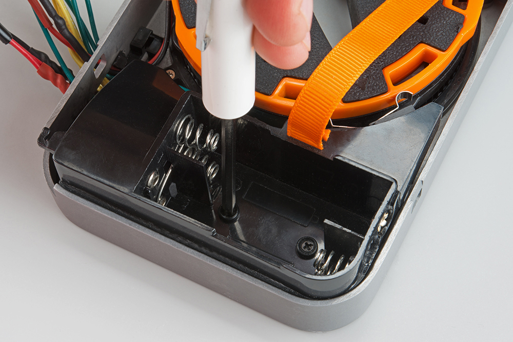
If you plan to wire up the limit switches (a good idea), now is a good time to remove the battery holder. Unscrew the two black Phillips screws from the bottom of the battery holder (underneath where the batteries would go), and carefully remove the holder.
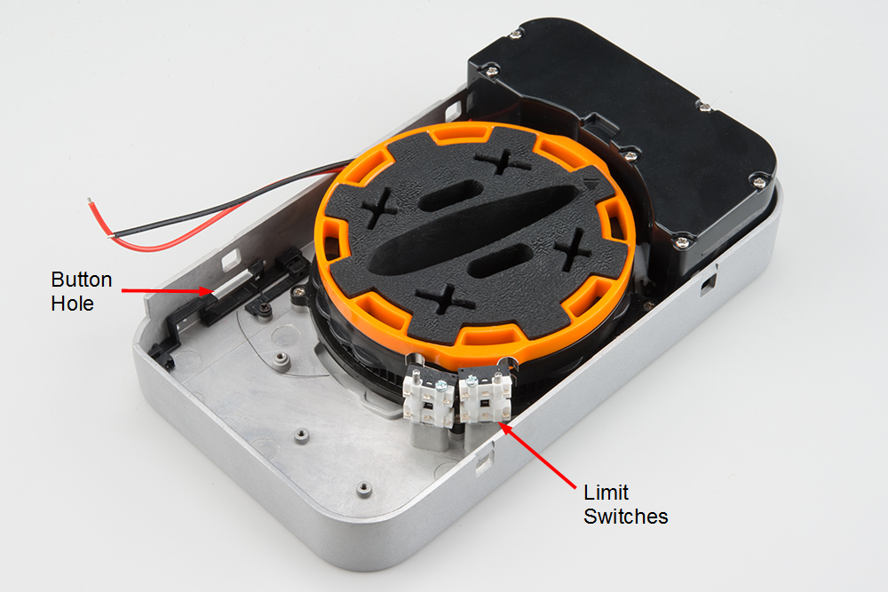
- Limit Switches - There are 4 limit switches that are pressed whenever one of the "bumps" on the rings moves by. The top 2 switches coincide with the "bumps" on the inner ring (orange), and the bottom 2 switches look for "bumps" on the outer ring (black).
- Button hole - On the original Lockitron, a button stuck out of this hole that allowed you to configure the Lockitron's wireless properties. Since we don't have the original electronics, we are going to use the hole to route wires out of the Lockitron housing.
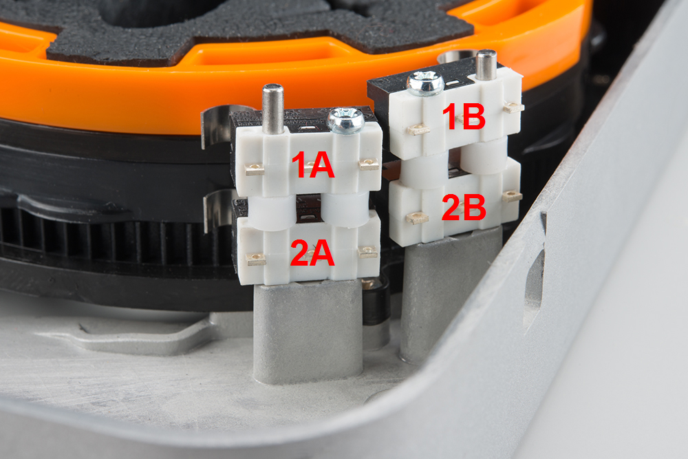
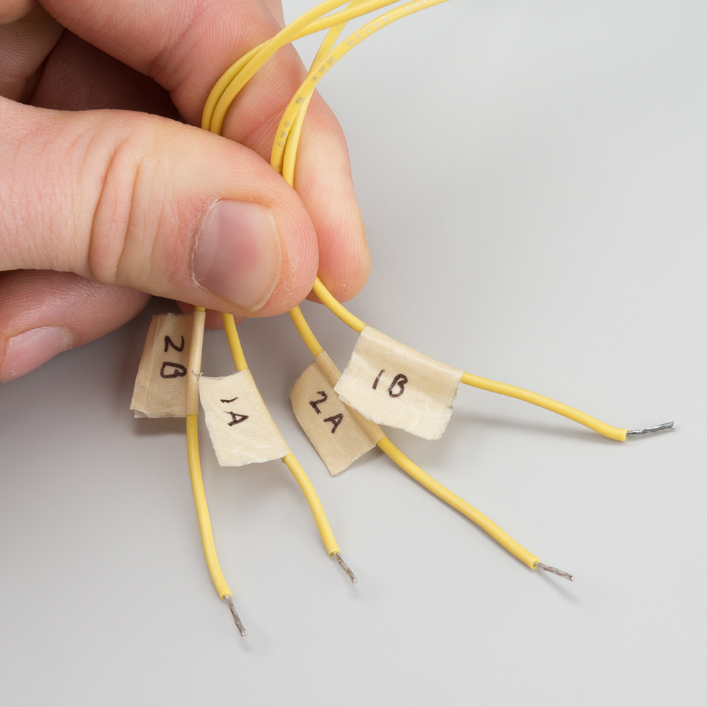
We are going to assign arbitrary names to the limit switches so that we know what to call them in our code. We also recommend labeling the wires (e.g. with a piece of tape and a pen) that are connected to the limit switches. When we put the battery housing back in the Lockitron, it will be very difficult to see which wire connects to which switch.
- 1A - First to be hit when the inner ring (orange) spins counterclockwise.
- 1B - First to be hit when the inner ring (orange) spins clockwise.
- 2A - First to be hit when the outer ring (black) spins counterclockwise.
- 2B - First to be hit when the outer ring (black) spins clockwise.
Hardware Hookup
Hook up Wires
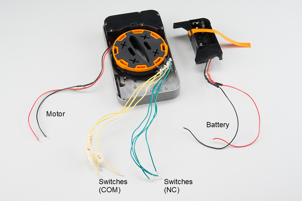
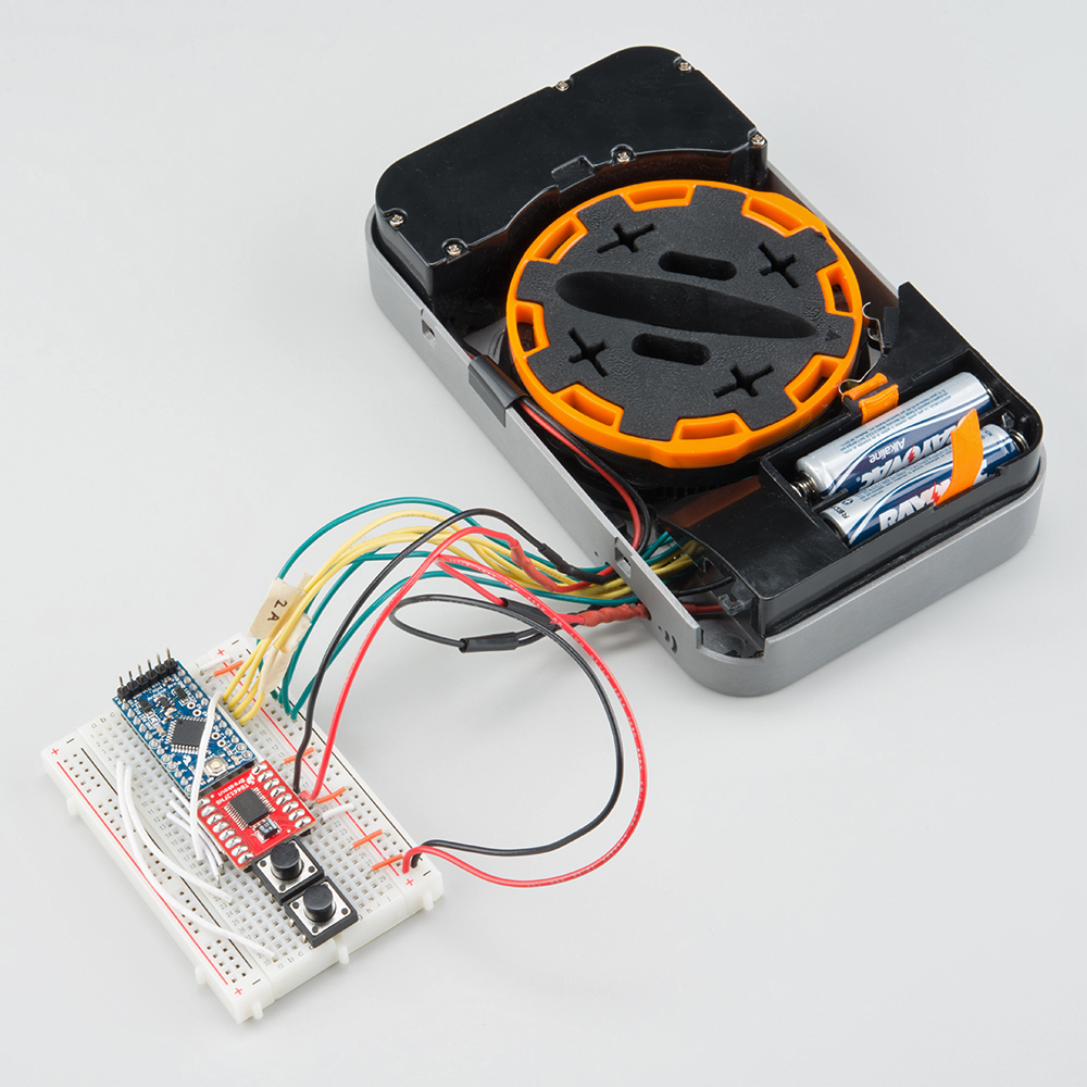
We first want to connect a set of wires to the limit switches, motor, and battery compartment. In the end, we should have something like the picture below. The following steps will show you how to get there.
Connect Wires to the Switches
Unscrew the battery holder, and set it aside (if you have not done so already). Examine the limit switches.
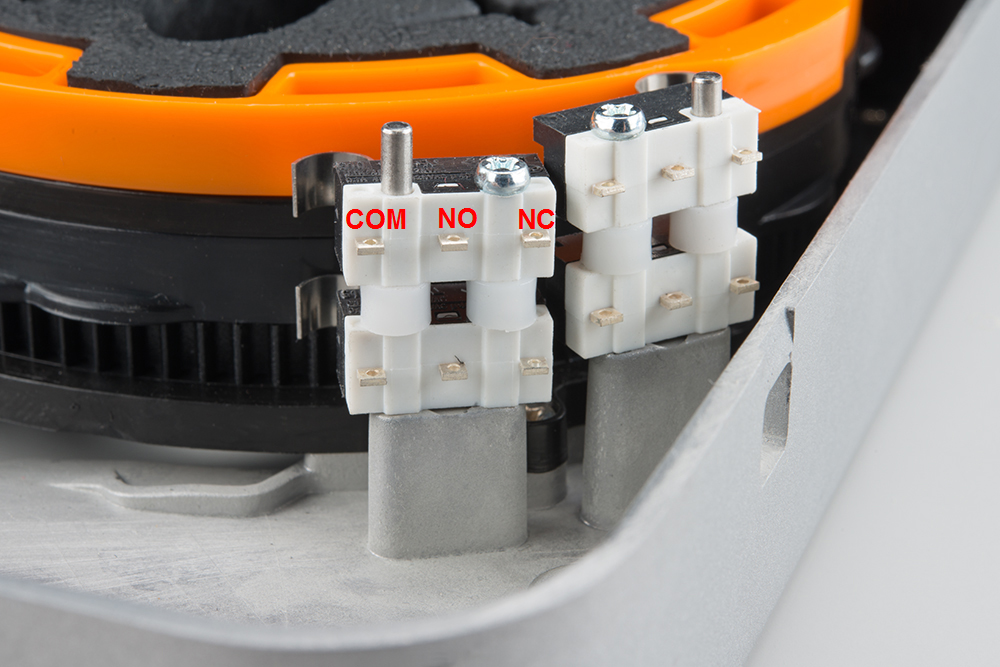
- COM - Common terminal
- NO - Normally open. The COM and NO terminals are connected when the switch is engaged.
- NC - Normally closed. The COM and NC terminals are connected when the switch is not engaged.
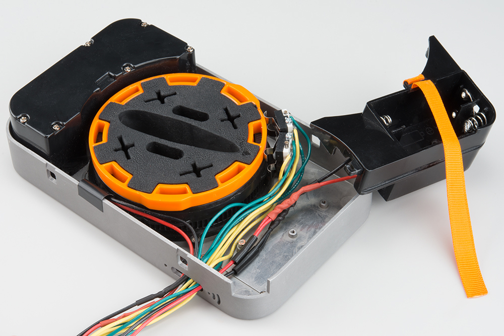
Cut, strip, and tin 8x 6-8 inch wires (I used 4 green and 4 yellow wires). Solder them to the outermost terminals on the limit switches. We will be using the COM and NC terminals.
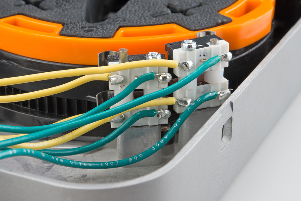
We recommend you label the wires so you know to which switch it is connected. In this instance, I tagged all the yellow (COM) wires with their respective switch (1A, 1B, 2A, 2B). I plan to connect the green wires (NC) all to ground and the yellow wires (COM) to individual Arduino pins.
Extend the Motor Wires
Cut, strip, and tin another 2x 6-8 inch wires for the motor. Use your favorite wire splicing technique (here are some good ones: 1, 2, 3) to connect to the motor wires. I used red and black to keep with the + and - theme.
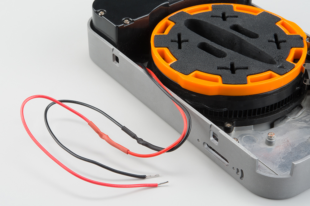
Extend the Battery Wires
Once again, cut, strip, and tin another set of wires for the batteries. You will need 2x 6-8 inch wires. Use your favorite splicing technique to connect to the battery wires. I used red and black wires to connect to + and -, respectively.

Route Wires out of the Housing
Carefully pull all the wires through the button opening in the housing.
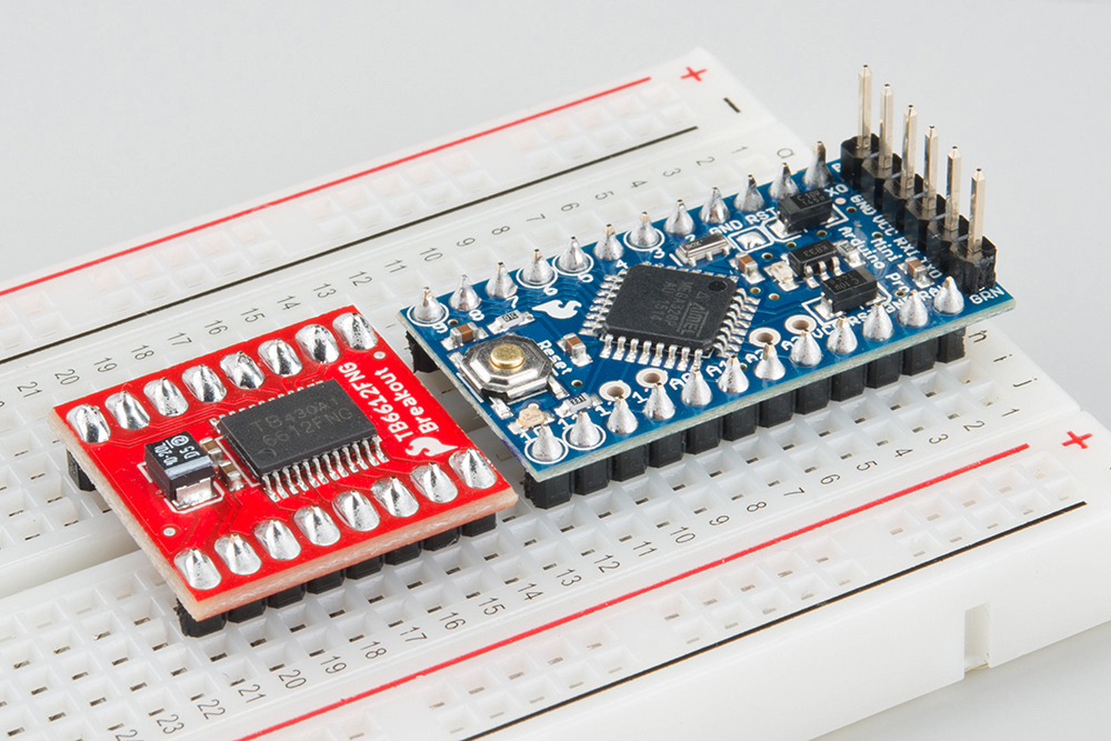
Solder Headers
Solder headers onto the Pro Mini and Motor Driver board. Don't forget to add headers to the programming port of the Pro Mini (the part where you attach the FTDI breakout).
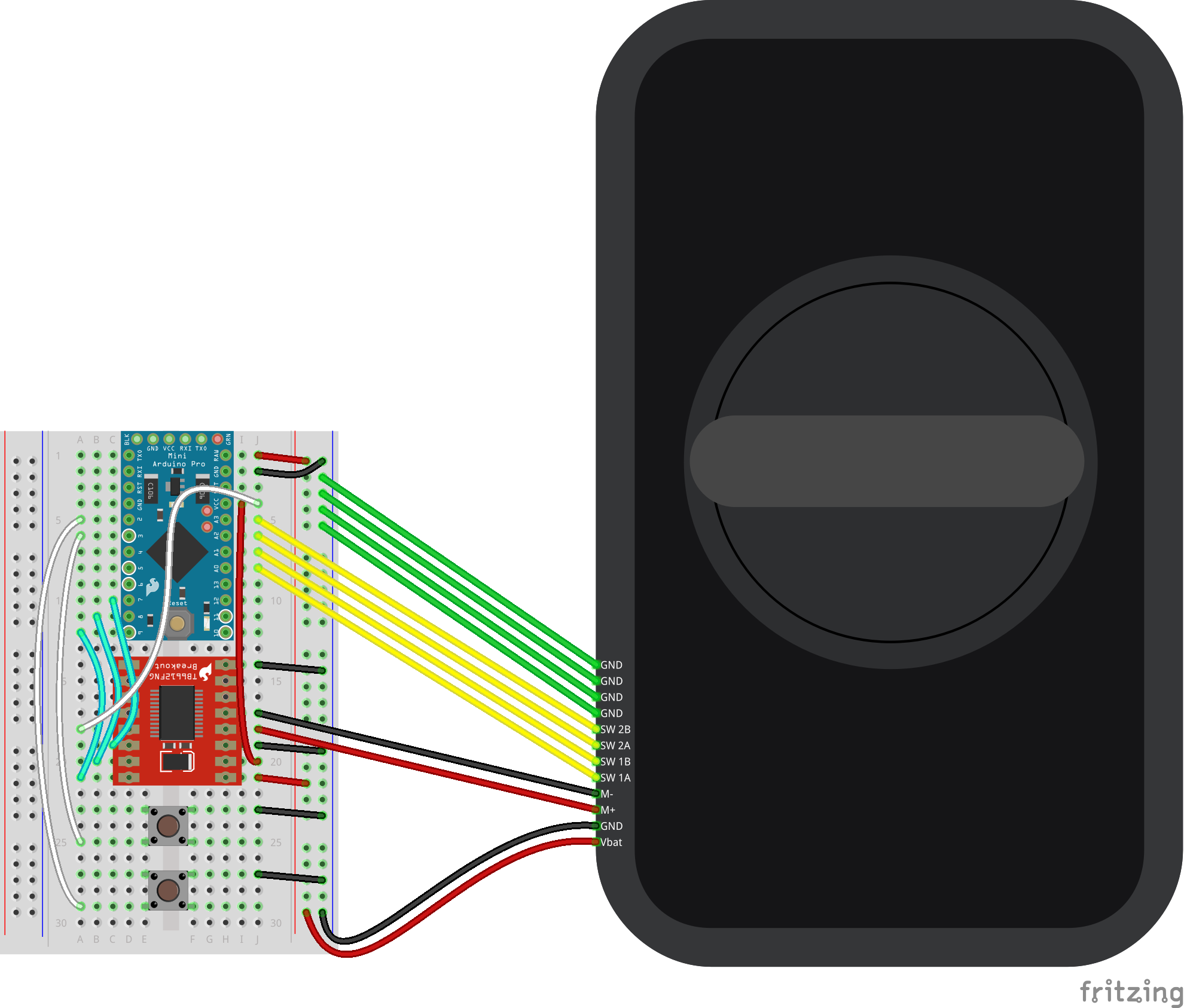
Attach Everything to a Breadboard
Attach the Pro Mini, Motor Driver board, and 2 buttons to the breadboard. Connect the wires from the Lockitron to the breadboard and add additional wires as shown.
Replace Battery Holder
Screw the battery holder back in place, making sure that the limit switch wires do not get caught underneath. Do not add batteries at this time.
Example Code
With all of the wires connected, we can upload some code to the Pro Mini.
Note: This example assumes you are using the latest version of the Arduino IDE on your desktop. If this is your first time using Arduino, please review our tutorial on installing the Arduino IDE.
If you have not previously installed an Arduino library, please check out our installation guide.- You generally don't want to control your door lock with just 2 buttons. You will probably want to add Bluetooth, RFID, fingerprint scanning, etc.
- Also, the code runs a "reset" loop when if first boots up. This just moves the two rings into a known setting that should fit on most locks. You will want to modify this part of the code for your own door (or, at the very least, let it run before installing the Lockitron) so you don't draw too much continuous current through the motor driver board if it gets stuck trying to move the deadbolt.
Example Sketch
Plug in the FTDI breakout to your Pro Mini, and connect a USB cable from it to your computer. Copy and paste the code into your Arduino IDE.
language:c
    /****************************************************************
Lockitron_Demo.ino
Shawn Hymel @ SparkFun Electronics
July 7, 2015

Controls the lock and unlock functions of a Lockitron motor with
2 buttons. Note that on boot, the Arduino will attempt to rotate
the motor to a "home" position. This might be bad if the
Lockitron in on a door.

This code is beerware; if you see me (or any other SparkFun
employee) at the local, and you've found our code helpful, please
buy us a round!

Distributed as-is; no warranty is given.
****************************************************************/

// Debug mode. 0 = Motor functional. 1 = Serial output only.
#define DEBUG 0

// Constants
const uint8_t LOCK_OPEN = 0;
const uint8_t LOCK_CLOSED = 1;
const uint8_t MSG_LOCK = 0x10;
const uint8_t MSG_UNLOCK = 0x11;
const uint8_t MSG_STATE_REQ = 0x12;

// Motor speed and direction definitions
const uint8_t MOTOR_SPEED = 200;
const uint8_t MOTOR_CW = 0;
const uint8_t MOTOR_CCW = 1;

// Pin definitions
const uint8_t BTN_UNLOCK_PIN = 2;
const uint8_t BTN_LOCK_PIN = 3;
const uint8_t SW_1A_PIN = A0;
const uint8_t SW_1B_PIN = A1;
const uint8_t SW_2A_PIN = A2;
const uint8_t SW_2B_PIN = A3;
const uint8_t AIN1_PIN = 7;
const uint8_t AIN2_PIN = 8;
const uint8_t PWMA_PIN = 9;

// Button states
uint8_t btn_lock;
uint8_t btn_unlock;
uint8_t prev_btn_lock;
uint8_t prev_btn_unlock;

// Switch state variables
uint8_t sw_1a;
uint8_t sw_1b;
uint8_t sw_2a;
uint8_t sw_2b;

// Lock state
uint8_t lock_state;

void setup() {

#if DEBUG
  Serial.begin(9600);
#else
  // Set up motor pins
  pinMode(AIN1_PIN, OUTPUT);
  pinMode(AIN2_PIN, OUTPUT);
  pinMode(PWMA_PIN, OUTPUT);
#endif

  // Set up switch and button pins
  pinMode(BTN_UNLOCK_PIN, INPUT_PULLUP);
  pinMode(BTN_LOCK_PIN, INPUT_PULLUP);
  pinMode(SW_1A_PIN, INPUT_PULLUP);
  pinMode(SW_1B_PIN, INPUT_PULLUP);
  pinMode(SW_2A_PIN, INPUT_PULLUP);
  pinMode(SW_2B_PIN, INPUT_PULLUP);

  // Reset the lock to unlocked position
  resetLock();
  lock_state = LOCK_OPEN;
  prev_btn_lock = 1;
  prev_btn_unlock = 1;
}

void loop() {

#if DEBUG

  // Read pins
  sw_1a = digitalRead(SW_1A_PIN);
  sw_1b = digitalRead(SW_1B_PIN);
  sw_2a = digitalRead(SW_2A_PIN);
  sw_2b = digitalRead(SW_2B_PIN);

  // Print results
  Serial.print("1A:");
  Serial.print(sw_1a);
  Serial.print(" 1B:");
  Serial.print(sw_1b);
  Serial.print(" 2A:");
  Serial.print(sw_2a);
  Serial.print(" 2B:");
  Serial.print(sw_2b);
  Serial.println();

  delay(100);

#endif

  // Read button states and lock or unlock on push
  btn_lock = digitalRead(BTN_LOCK_PIN);
  btn_unlock = digitalRead(BTN_UNLOCK_PIN);
  if ( (btn_lock == 0) && (prev_btn_lock == 1) ) {
#if DEBUG
    Serial.println("Locking");
#else
    lock();
#endif
  }
  if ( (btn_unlock == 0) && (prev_btn_unlock == 1) ) {
#if DEBUG
    Serial.println("Unlocking");
#else
    unlock();
#endif
  }
  prev_btn_lock = btn_lock;
  prev_btn_unlock = btn_unlock;
}

void resetLock()
{
  // Move motor to reset its position
  moveMotor(MOTOR_SPEED, MOTOR_CCW);
  do
  {
    sw_1a = digitalRead(SW_1A_PIN);
    sw_1b = digitalRead(SW_1B_PIN);
    sw_2a = digitalRead(SW_2A_PIN);
    sw_2b = digitalRead(SW_2B_PIN);
  }
  while ( !((sw_2a == 1) && (sw_2b == 1)));
  stopMotor();
}

void lock()
{
  // Move motor to lock the deadbolt
  moveMotor(MOTOR_SPEED, MOTOR_CW);
  do
  {
    sw_1a = digitalRead(SW_1A_PIN);
    sw_1b = digitalRead(SW_1B_PIN);
    sw_2a = digitalRead(SW_2A_PIN);
    sw_2b = digitalRead(SW_2B_PIN);
  }
  while ( !((sw_1a == 0) && (sw_1b == 1) &&
            (sw_2a == 0) && (sw_2b == 1)) );
  stopMotor();
  delay(100);

  // Move motor back to starting position
  moveMotor(MOTOR_SPEED, MOTOR_CCW);
  do
  {
    sw_1a = digitalRead(SW_1A_PIN);
    sw_1b = digitalRead(SW_1B_PIN);
    sw_2a = digitalRead(SW_2A_PIN);
    sw_2b = digitalRead(SW_2B_PIN);
  }
  while ( !((sw_2a == 1) && (sw_2b == 1)) );
  stopMotor();
  lock_state = LOCK_OPEN;
}

void unlock()
{
  // Move motor to lock the deadbolt
  moveMotor(MOTOR_SPEED, MOTOR_CCW);
  do
  {
    sw_1a = digitalRead(SW_1A_PIN);
    sw_1b = digitalRead(SW_1B_PIN);
    sw_2a = digitalRead(SW_2A_PIN);
    sw_2b = digitalRead(SW_2B_PIN);
  }
  while ( !((sw_1a == 1) && (sw_1b == 0) &&
            (sw_2a == 1) && (sw_2b == 0) ));
  stopMotor();
  delay(100);

  // Move motor back to starting position
  moveMotor(MOTOR_SPEED, MOTOR_CW);
  do
  {
    sw_1a = digitalRead(SW_1A_PIN);
    sw_1b = digitalRead(SW_1B_PIN);
    sw_2a = digitalRead(SW_2A_PIN);
    sw_2b = digitalRead(SW_2B_PIN);
  }
  while ( !((sw_2a == 1) && (sw_2b == 1)) );
  stopMotor();
  lock_state = LOCK_CLOSED;
}

void moveMotor(uint8_t spd, uint8_t dir)
{
  boolean ain1;
  boolean ain2;

  // Define direction pins
  if ( dir )
  {
    ain1 = HIGH;
    ain2 = LOW;
  }
  else
  {
    ain1 = LOW;
    ain2 = HIGH;
  }

  // Set motor to GO!
  digitalWrite(AIN1_PIN, ain1);
  digitalWrite(AIN2_PIN, ain2);
  analogWrite(PWMA_PIN, spd);
}

void stopMotor()
{
  analogWrite(PWMA_PIN, 0);
}
Run
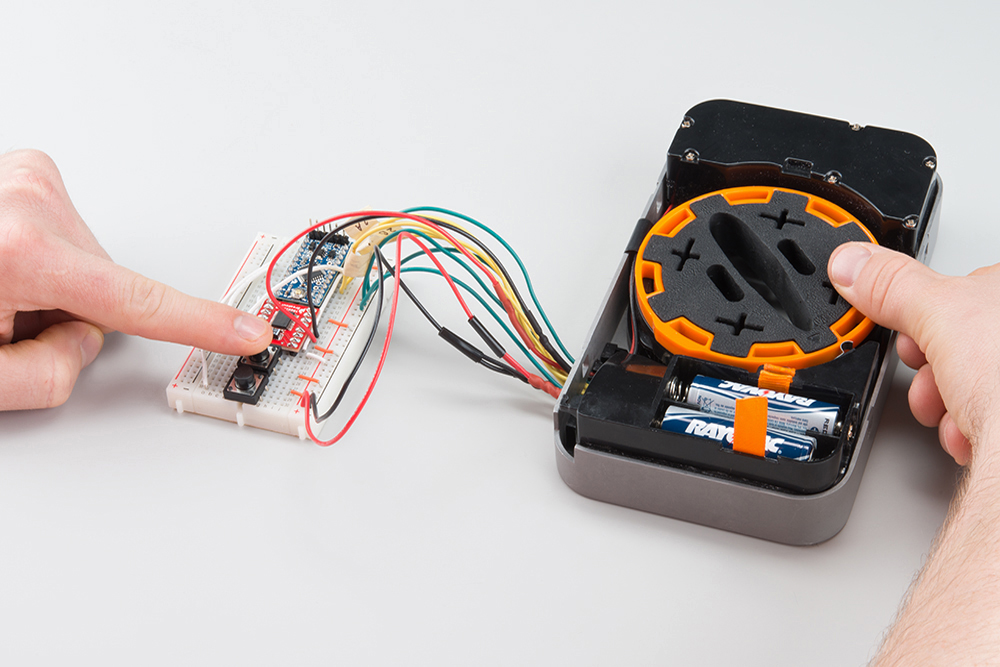
Once the program has successfully uploaded to your Pro Mini, disconnect the FTDI breakout from the Pro Mini. Add 4x AA batteries to the battery holder, and the motor should rotate to a "home" position.
Try pushing the two buttons to mimic the "lock" (top button) and "unlock" (bottom button) functions.
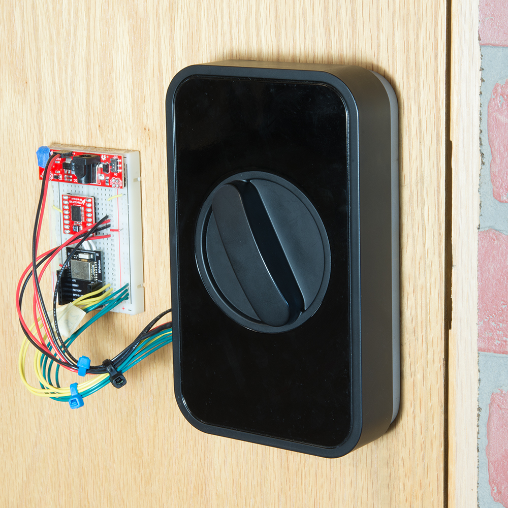
Installation
The fine folks at Lockitron made a fantastic video showing how to install the Lockitron device. We skipped past the first 1:14 of the video, which shows how to connect the Electric Imp in the housing to WiFi (we don't need that; we made our own electronics!).
If you want to mount the breadboard next to the Lockitron, you can use the sticky tape on the back of the breadboard or add your own tape/glue.
Once you have everything working, you can always enclose the electronics for added security.
Resources and Going Further
The Lockitron is a great way to add some advanced technology to your door and venture into the world of home automation. This guide, hopefully, helped show you how to use the Lockitron Mechanical Assembly. From here, the possibilities are endless on how you want to control your door:
- Secret knock code
- Bluetooth app on your smartphone
- Connected to a webpage
- RFID
- Fingerprint scanner
- Iris scanner
- Voice commands
Resources
Other Tutorials
Need inspiration on how to interact with the Lockitron? Check out these tutorials: