BC118 BLE Mate 2 Hookup Guide
 SFUptownMaker
Introduction
SparkFun's Bluetooth low energy (BLE) Mate 2 is a no-nonsense Bluetooth 4.0 (aka Bluetooth low energy or Bluetooth Smart) development board related to our Bluetooth Mate Silver and Bluetooth Mate Gold.
The BLE Mate 2 only supports Bluetooth 4.0; it won't connect to older devices. It's also worth noting that BLE does not support a Serial Port Protocol as older versions of Bluetooth did; that makes interoperability between BLE dongles, devices, and modules harder than with Bluetooth Classic.
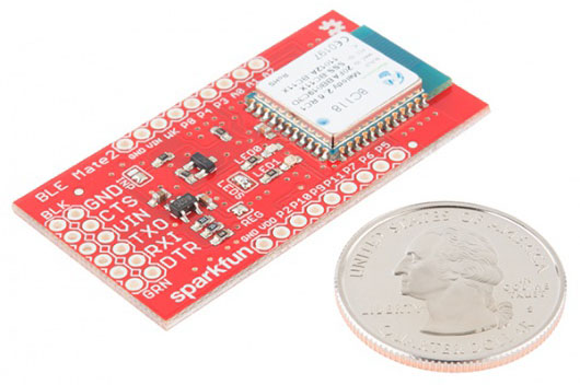
As you can see, the BLE Mate 2 is a small board: 1.0" by 1.95" (25mm x 50mm). The six-pin header on the end opposite the module is a "host" serial pinout, the same as that on the FTDI Basic boards, which allows the BLE Mate 2 to be connected directly to any device with a matching header, such as the SparkFun Arduino Pro and Pro Mini. Coupled with the FTDI SmartBasic, you can even develop your code without having to swap cables! The board has built-in level translation, so it can be used with boards of higher voltage than the 3.3V default used by the BC118.
You'll also notice that there are breakout holes available for all the pins on the BC118 module; we'll cover the use of those in a later section.
Covered in this Tutorial:
- Hardware hookup of the BLE Mate 2
- BC118 functionality
- BLE Mate 2 library and example code
Materials Used
- Arduino Pro 5V - You could just as easily use the 3.3V version, or the Pro Mini, or (in fact) any board that supports serial communications.
- BLE Mate 2 (natch) - Depending on what you want to do, you may need two of these. We'll demonstrate an example connecting to another BLE Mate 2 as well as providing some application examples showing how to connect to an iPhone or an Android device.
- FTDI SmartBasic - The SmartBasic was designed for just this application--to allow an Arduino to be programmed while allowing the hardware serial port to be selectively attached to another serial device. It's not recommended that you use a software-controlled serial port for this application as the data flow from the BLE Mate 2 can easily overwhelm the buffer.
- Snappable male header pins - You'll need to add pins to the SmartBasic and the BLE Mate 2 (if you want to plug the BLE Mate 2 into a breadboard).
- 6- and 8-pin female headers - at a minimum. You'll want a 6-pin female for the BLE Mate and the SmartBasic and an 8-pin for the Pro.
- Jumper wires - You really only need one of these, to connect the Arduino Pro to the OE line on the SmartBasic.
Recommended Reading
Before you go any further, you may want to review some of these other tutorials:
- Loading an Arduino Library - There is a library available for the BC118 module on the BLE Mate 2 github repository, and this tutorial will explain how to load it.
- Hexadecimal - A lot of the parameters used by the BC118 are in hexadecimal; brush up on what that means with this tutorial!
- Bluetooth Basics - Learn some of the basics of how Bluetooth works.
Hardware Overview
Let's take a look at the BLE Mate 2 board.
Front
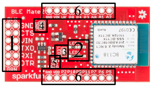
The image above has the major parts of the BLE Mate 2 labeled. We'll start with the front, since it's more interesting. We're just going to apply labels to things here; we'll discuss their full use on the next page.
- 6-pin FTDI Basic compatible serial header - This header has the same pinout as that of an FTDI Basic board; it's meant to connect to a client device such as an Arduino Pro. If you want to connect it to an FTDI Basic board, you'll need to either make or buy a crossover adapter. We've provide two rows of pins to make multiple connections to these pins (e.g. to sniff the signals for troubleshooting) easier.
- LED0 and LED1 - These LEDs display information about the current state of the module. These LEDs reflect the logical state of the module, and a reset of the module may be needed before the settings take effect. More on that later.
- LEDs jumper - this jumper ships closed with solder; clear the jumper to disable the LEDs and save some current for low-power situations.
- INP jumper - this jumper connects the voltage input pin on the 6-pin header to the 3.3V regulator on the BLE Mate 2. It can be cleared to remove the regulator from the circuit and save current.
- REG jumper - clearing this jumper will break the connection between the output of the 3.3V regulator and the supply of the BC118 module.
- GPIO headers - All the pins on the BC118 are broken out to these pins, as are power and ground.
Back
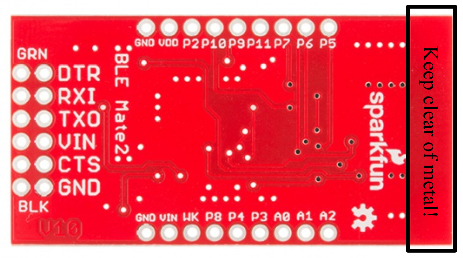
The back is much simpler. You'll note that all the pin labels are present on this side as well.
The one thing that is really worth pointing out from this side is the keepout at the top of the board. You can see that the ground plane only extends so far up the PCB; for best performance, you should try and keep that area free of any metal when embedding the BLE Mate 2 in a project. Failing to do so may result in interference or a loss of signal strength.
Hardware Connection
This page will cover both general hardware connection for the BLE Mate 2 as well as specific information for this tutorial.
6-pin Serial Header
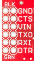
The pinout on this header matches that of the FTDI Basic boards, so it can be used anywhere an FTDI basic can be. However, it's probably not fast enough to do any kind of wireless bootloading.
- DTR - Connected only to the other DTR pad. This pin can be connected to PIO5 to provide a DTR output to the client device; that signal will be at a voltage determined by the supply voltage of the BC118 module and so may not be adequate to drive the reset signal on an Arduino.
- RXI - Data IN from the client device.
- TDO - Data OUT from the BC118 device. Shifted up to the level on the VCC pin of this header.
- VCC - Connected to the INP jumper (see below).
- CTS - Connected only to the other CTS pad. Can be connected to PIO6 to provide an RTS signal to the BC118. That signal must not exceed the supply voltage of the BC118 module.
- GND - Negative supply rail for the entire module.
GPIO Headers
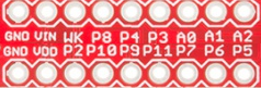
There are two 0.1" (2.54mm) headers along the sides of the module. These pins are 0.9" (22.5mm) apart, so they'll fit into a breadboard (although not a lot of space will be left outside the pins!)
The currently useful pins on the BC118 module are all broken out to these headers; I'll go over what they do and what they can do. Here, I'll talk about commands and configuration parameters on the next page, but they will be referenced below.
- **AIO2 **- By default, this is an analog input, which can be read by sending the command "AIO 2" to the module. The module will respond with the voltage on this pin, in mV. If the "ACFG" parameter is "ON", this pin will reflect the module's state: HIGH if the module is connected or LOW if the module is not.
- AIO1 - Default function is same as AIO2. If the "ACFG" parameter is "ON", pulling this pin HIGH will enable transparent mode, causing data presented to the RX pin to be sent verbatim to any connected device.
- AIO0 - Default function is same as AIO2. If "ACFG" is "ON", this pin determines the module's role at boot time. If the signal is HIGH, the module will boot into Central mode. If LOW, Peripheral mode.
- P3 - GPIO3. Default is to either mirror from or mirror to another connected device. More on this later.
- P4 - LED0 output.
- P8 - By default, exit transparent mode. Can be configured as an IO pin for mirroring by setting the "GPIO" parameter to "OFF"
- WK - Dependent upon the "WAKE" and "WLVL" parameters, this pin can be used to wake the device from hibernation.
- VIN - This pin connects to the INP jumper. More on this below.
- GND - Ground for the entire circuit.
- P5 - When parameter "FCTR" is "ON", this will be a CTS output from the BC118.
- P6 - When parameter "FCTR" is "ON", this will be an RTS input to the BC118.
- P7 - GPIO7. See P3 above.
- P11 - GPIO11. See P3 above.
- P9 - LED1 output.
- P10 - GPIO10. See P3 above.
- P2 - Not currently enabled.
- VDD - This pin ties directly to the supply rail of the BC118. It must be kept between 1.8V and 4.3V to avoid damage to the module.
- GND - Ground for the entire circuit.
LEDs

As mentioned on the previous page, LEDs 0 and 1 provide some easily accessible feedback on the current state of the module. Here's a decoder ring for sorting out what they mean.
| LED 0 Blue |
LED 1 Red |
Status |
|---|---|---|
| BLINK | OFF | Scanning |
| OFF | BLINK | Advertising |
| ON | OFF | Connected Central |
| OFF | ON | Connect Peripheral |
| ON | ON | Idle |
Note: the LEDs will change to represent the current settings of the module when changing into scanning, advertising, or idle modes, but the module will not change state until the changes have been written to non-volatile memory and the module has been rebooted.
LEDS Jumper
This jumper disconnects the cathode side of the LEDs from the ground plane, disabling them and eliminating the few hundred microamps each one draws under normal circumstances. It ships closed by default.
INP and REG Jumpers

The INP jumper, pictured above, has four possible configurations but only three valid ones.
This is the default mode, as it ships. In this mode, the input voltage from the VCC pin on the 6-pin header and the VIN pin on the GPIO header is routed to the 3.3V regulator.

In this mode, the input side of the regulator is disconnected from all pins, and the module's supply is connected directly to the VIN pin and the VCC pin. In this situation, the voltage present on the input must be between 1.8V and 4.3V. That's within the range of a single-cell LiPo battery, but not of a 5V target board!
It's probably a good idea to clear the REG jumper at this point, too; putting a voltage on the output of the regulator but not on the input is liable to cause odd behavior.
The level shifting circuit is still active here, so if the data lines on your processor are at a higher voltage than the BC118 is being fed, communications will still work.

With no solder on the jumper, you've completely disconnected the module from the VCC and VIN pins entirely. You'll need to provide power to the 3.3V pin on the GPIO header directly, with the same caveat as earlier regarding the voltage range.
Again, you should clear the REG jumper.
Finally, the fourth mode, which I'm not only going to include a picture of, it's so inappropriate: a big old solder glob covering all three pads. Don't do this. Seriously. It probably won't do anything bad, but it's not going to help your current consumption any, it may damage the regulator, and it will bypass the regulator. Just don't do it.
BC118 Functionality
While you can just skip over this page and go straight to the code example and library documentation, it's probably a good idea to at least skim it so you have some idea what's going on under the hood.
Concepts
The BC118 realizes a custom BLE profile, so you'll have to take that into account when developing an app for it. It also means you won't be able to easily connect it to any other BLE modules other than another BC118.
Generally, when you change settings on the BC118, you need to write the settings to the onboard non-volatile memory and reset the module before they will take effect. When in doubt, write/reset--it's the only way to be sure.
When the module boots in Central mode, it will immediately begin scanning and will scan until it reaches the timeout period (which may be never). To connect to a Peripheral devices, the BC118 must be in Central mode, and scanning. This makes programmatically detecting a successful connection difficult, as the acknowledgment of the connection is buried in a stream of detected devices. The BLE Mate 2 library takes care of that for you.
Communication With the Module
From the factory, the BC118 comes programmed to accept and transmit via the UART at 9600bps. There are two types of transactions the user can initiate with the module: Commands and setting/getting parameters.
The BC118 expects a carriage return ('\r') at the end of a command string; if you send a newline ('\n')(which is frequently a standard practice in serial communications; the Arduino println() function sends "\n\r" at the end of the transmission), that will cause a receive error.
All responses from the BC118 will be ended with "\n\r", however, which makes that a good string pattern to recognize for detecting responses from the module. If the module was unable to parse the string between the last two carriage returns into a command, it will respond with "ERR\n\r". At that point, the buffer is clear, and that fact can be a useful way to get to a known state for re-synchronizing user code with the buffer in the BC118.
Finally, regarding "transparent" mode: it's possible to put the module into transparent mode, where it forwards data presented on the UART directly to the remote device, and forwards data received from the remote device directly to the UART. Unfortunately, once transparent mode has been activated, there's no escape sequence that can be sent across the UART to return to data mode. GPIO8 and AIO1 can be used to exit transparent mode, but only if that function has been enabled (by setting the parameters GPIO and ACFG to ON, respectively). If those parameters haven't been set, and transparent mode is entered, the only way out is to power cycle the module.
Useful Commands
Here's a list of useful commands. For more information, you can refer to the Melody Smart User Manual on the BlueCreation website.
Commands will be presented with the command first, then parameters to be passed afterwards in parentheses after the command, but the parentheses are not part of the command. Optional parameters will be in brackets. A pipe ('|') will be used to separate "choose one of these" parameters.
- ADV (ON|OFF) - Turn advertising on or off. While this can be toggled without error in Central mode, it will have no effect.
- AIO (0|1|2) - Report the analog voltage, in mV, on the respective analog input pin.
- CON [(BT ADDRESS) (TYPE)] **- **Device must be in scan mode for this command to work! If parameter ACON is '1', no parameter needs to be passed to this command and the module will connect to the first target that supports the Melody Smart protocol (i.e., another BC118 or an app you've written on a target device). Otherwise, BT ADDRESS should be the full 12-character hex address of the device to connect to, and type should be 0 for a public address (most common) or 1 for a private address.
- DCN - Disconnect from remote device. Works in either peripheral or central mode.
- HIB (timeout) - The "timeout" parameter should be an integer value between 1050 and 429496795, and represents the number of 1.024ms periods to elapse before the device emerges from hibernation. Restarting from hibernation is a clean reboot to stored settings.
- GET (parameter) - Returns the value of (parameter), which can be any of the configuration parameters listed below.
- RST - Resets the chip, loading all settings from non-volatile memory.
- RTR - Restores all settings to factory defaults.
- SCN (ON|OFF) - Enable or disable scanning.
- SET (parameter)=(value) - No spaces around the equal sign! Set (parameter) to (value). Settings changed in this way will not persist through a reset or power cycle unless the WRT command is issued (see below).
- SND (data) - Send a stream of binary data. At most, 20 characters can be sent when in Central mode and 125 in Peripheral mode, and the data must not contain a newline ('\r' or 0x0D) as that will trigger transmission.
- STS - Return the status of the module.
- VER - Return the version of Melody Smart on the current module, and the module's 12-character Bluetooth address.
- WRT - Save the current settings to non-volatile memory, causing them to persist after a reset or power cycle. Note that many settings require a WRT/RST cycle to actually take effect!
Parameters
In addition to the commands listed above, there are some parameters governing the behavior of the module which can be set or checked via the SET and GET commands mentioned above. Here are some of the most important ones.
- ACFG=(ON|OFF) - When OFF, AIO pins are available as analog inputs. When ON, they can be used for control and reporting (see the "Hardware Connection" page for details).
- ACON=(ON|OFF) - When ON, the module will connect to the first discovered compatible device. This may not be the device you want to connect to!
- ADVC=(ON|OFF) - When ON, the device advertises constantly if not connected.
- ADVP=(SLOW|FAST) - Advertising rate. Using SLOW will consume less power but make connecting to the module slower.
- ADVT=(timeout) - How long the device will advertise after advertising begins (either at boot or due to the ADV command). Values range from 0 (forever) to 4260, and are integer representations of seconds.
- CENT=(ON|OFF) - Enable or disable Central mode. Must WRT/RST to make this take effect!
- CCON=(ON|OFF) - Should the device scan/advertise upon disconnection?
- CONP=(max_conn_int) (min_conn_int) (latency) (timeout) - Settings this device will send to a Central connecting to it. (max_conn_int) must be greater than (min_conn_int), and both must be between 6 and 3200 and represent the connection interval in units of 1.25ms each. They represent the longest and shortest intervals between which the Central device will ask for data. (latency) is in terms of connection intervals and represents the connection slave latency, which is the number of periods the Peripheral will ignore the Central if it has no new data. Finally (timeout) is the connection supervision timeout, the longest period the Central device should wait before declaring the link lost. It's an integer, in units of 10ms.
Arduino Library Example
If you haven't done so yet, download the .zip file of the BLE Mate 2 GitHub repository and install the Arduino library from the "Arduino/libraries" sub directory.
The Example
There's an example in the repository that can be accessed through the "Examples" menu in Arduino. It'll show you how to use all the various functions in the library to connect two BLE Mate 2 boards. First, connect your hardware like so...
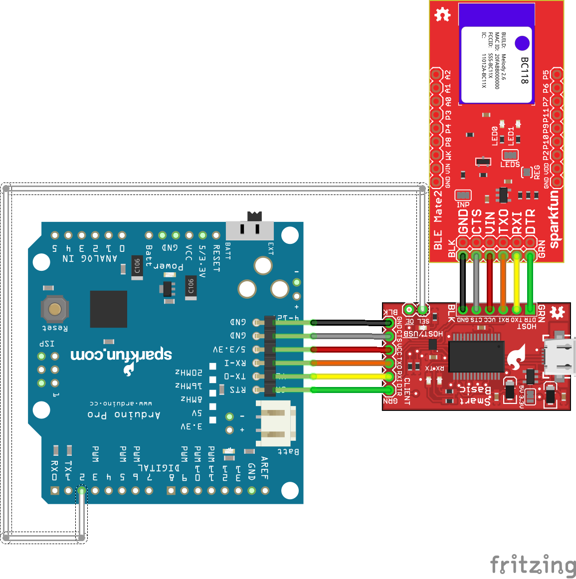
I've reproduced the code in its entirety below.
language:c
/****************************************************************
Code to demonstrate the use of the BC118 BLE module on the
BLE Mate 2 board by SparkFun electronics.


15 Nov 2014 - Mike Hord, SparkFun Electronics

Code developed in Arduino 1.0.6, on an Arduino Pro 5V, using a
SparkFun SmartBasic board to multiplex uploading and serial
output.
****************************************************************/

#include <SparkFun_BLEMate2.h>

// You can also create a SoftwareSerial port object and pass that to the
//  BLEMate2 constructor; I don't recommend that because it's very possible
//  for the amount of traffic coming from the BC118 to overwhelm the fairly
//  shallow buffer of the SoftwareSerial object.
BLEMate2 BTModu(&Serial);

// This boolean determines whether we're going to do a central or peripheral
//  example with this code.

boolean central = true;

void setup()
{
  pinMode(2, OUTPUT);    // Control for the SmartBasic. If you look at the
                         //  bottom of the sketch, you'll see that I've added
                         //  functions called "selectBLE()" and "selectPC()"
                         //  to make it a little more obvious when I switch
                         //  between serial devices.
  Serial.begin(9600);    // This is the BC118 default baud rate.
  selectBLE();           // Route serial data to the BC118.

  // Regarding function return values: most functions that interact with the
  //  BC118 will return BLEMate2::opResult values. The possible values here
  //  are:
  //  REMOTE_ERROR - No remote devices exist.
  //  INVALID_PARAM - You've called the function with an invalid parameter.
  //  TIMEOUT_ERROR - The BC118 failed to respond to the command in a timely
  //                   manner; timely is redefined for each command.
  //  MODULE_ERROR - The BC118 didn't like the command string it received.
  //                  This will probably only occur when you attempt to send
  //                  commands and parameters outside the built-ins.
  //  SUCCESS - What it says.

  // Reset is a blocking function which gives the BC118 a few seconds to reset.
  //  After a reset, the module will return to whatever settings are in
  //  non-volatile memory. One other *super* important thing it does is issue
  //  the "SCN OFF" command after the reset is completed. Why is this important?
  //  Because if the device is in central mode, it *will* be scanning on reset.
  //  No way to change that. The text traffic generated by the scanning will
  //  interfere with the firmware on the Arduino properly identifying response
  //  strings from the BC118.
  if (BTModu.reset() != BLEMate2::SUCCESS)
  {
    selectPC();
    Serial.println("Module reset error!");
    while (1);
  }

  // restore() resets the module to factory defaults; you'll need to perform
  //  a writeConfig() and reset() to make those settings take effect. We don't
  //  do that automatically because there may be things the user wants to
  //  change before committing the settings to non-volatile memory and
  //  resetting.
  if (BTModu.restore() != BLEMate2::SUCCESS)
  {
    selectPC();
    Serial.println("Module restore error!");
    while (1);
  }
  // writeConfig() stores the current settings in non-volatile memory, so they
  //  will be in place on the next reboot of the module. Note that some, but
  //  not all, settings changes require a reboot. It's probably in general best
  //  to write/reset when changing anything.
  if (BTModu.writeConfig() != BLEMate2::SUCCESS)
  {
    selectPC();
    Serial.println("Module write config error!");
    while (1);
  }
  // One more reset, to make the changes take effect.
  if (BTModu.reset() != BLEMate2::SUCCESS)
  {
    selectPC();
    Serial.println("Second module reset error!");
    while (1);
  }
  selectBLE();

  // NB!!!!!!!!!!!!! This write/reset thing is *really* important.
  //  The status command (STS) and the LEDs *will* lie to you and tell you that
  //  you are e.g. advertising or in central mode when in fact that is not the
  //  case and the module still needs to be reset before that is actually true.

  // Okay, now we're unquestionably set to default settings. That means we're
  //  set up as a peripheral device, advertising forever. You should be seeing
  //  a blinking red LED on the BLE Mate.

  // At this point the example branches. Down one branch, we'll explore what it
  //  means to go into central mode, find and connect to a BC118, send some
  //  data, and disconnect. Down the other, we'll sit around waiting for
  //  something (either another BC118 or a phone or something) to connect and
  //  send us some data.

  if (central)
  {
    setupCentralExample();
  }
  else
  {
    setupPeripheralExample();
  }
}

void loop()
{
  // Since I'm going to be reporting strings back over serial to the PC, I want
  //  to make sure that I'm (probably) not going to be looking away from the BLE
  //  device during a data receive period. I'll *guess* that, if more than 1000
  //  milliseconds has elapsed since my last receive, that I'm in a quiet zone
  //  and I can switch over to the PC to report what I've heard.
  static String fullBuffer = "";
  static long lastRXTime = millis();
  if (lastRXTime + 1000 < millis())
  {
    if (fullBuffer != "")
    {
      selectPC();
      Serial.println(fullBuffer);
      selectBLE();
      fullBuffer = "";
    }
  }
  static String inputBuffer;
  if (central)
  {
    doCentralExample(); // We're going to go to this function and never come
                        //  back, since we want to do the central connection
                        //  demo just once.
  }
  else
  {
    // This is the peripheral example code.

    // When a remote module connects to us, we'll start to see a bunch of stuff.
    //  Most of that is just overhead; we don't really care about it. All we
    //  *really* care about is data, and data looks like this:
    // RCV=20 char max msg\n\r

    // The state machine for capturing that can be pretty easy: when we've read
    //  in \n\r, check to see if the string began with "RCV=". If yes, do
    //  something. If no, discard it.
    while (Serial.available() > 0)
    {
      inputBuffer.concat((char)Serial.read());
      lastRXTime = millis();
    }

    // We'll probably see a lot of lines that end with \n\r- that's the default
    //  line ending for all the connect info messages, for instance. We can
    //  ignore all of them that don't start with "RCV=". Remember to clear your
    //  String object after you find \n\r!!!
    if (inputBuffer.endsWith("\n\r"))
    {
      if (inputBuffer.startsWith("RCV="))
      {
        inputBuffer.trim(); // Remove \n\r from end.
        inputBuffer.remove(0,4); // Remove RCV= from front.
        fullBuffer += inputBuffer;
        inputBuffer = "";
      }
      else
      {
        inputBuffer = "";
      }
    }
  }
}

void setupCentralExample()
{
  // We need to change some settings, first, to make this central mode thing
  //  work like we want.

  // When ACON is ON, the BC118 will connect to the first BC118 it discovers,
  //  whether you want it to or not. We'll disable that.
  BTModu.stdSetParam("ACON", "OFF");
  // When CCON is ON, the BC118 will immediately start doing something after
  //  it disconnects. In central mode, it immediately starts scanning, and
  //  in peripheral mode, it immediately starts advertising. We don't want it
  //  to scan without our permission, so let's disable that.
  BTModu.stdSetParam("CCON", "OFF");
  // Turn off advertising. You actually need to do this, or the presence of
  //  the advertising flag can confuse the firmware when the module is in
  //  central mode.
  BTModu.BLENoAdvertise();
  // Put the module in central mode.
  BTModu.BLECentral();
  // Store these changes.
  BTModu.writeConfig();
  // Reset the module. Write-reset is important here!!!!!!
  BTModu.reset();

  // The module is now configured to connect to another external device.
}

void doCentralExample()
{
  // We're going to tstart with an assumption of module error. That way, we
  //  can easily check against the result while we're iterating.
  BLEMate2::opResult result = BLEMate2::MODULE_ERROR;
  // This while loop will continue to scan the world for addresses until it
  //  finds some. Why? Why not?
  while(1)
  {
    selectBLE();
    result = BTModu.BLEScan(2);
    if (result == BLEMate2::SUCCESS)
    {
      selectPC();
      Serial.println("Success!");
      break;
    }
    else if (result == BLEMate2::REMOTE_ERROR)
    {
      selectPC();
      Serial.println("Remote error!");
    }
    else if (result == BLEMate2::MODULE_ERROR)
    {
      selectPC();
      Serial.println("Module error! Everybody panic!");
    }
  }

  byte numAddressesFound = BTModu.numAddresses();

  // BC118Address is where we'll store the index of the first BC118 device we
  //  find. We'll know it because the address will start with "20FABB". By
  //  starting at 10, we know when we've found something b/c it'll be 4 or less.
  byte BC118Address = 0;
  String address;

  selectPC();
  Serial.print("We found ");
  Serial.print(numAddressesFound);
  Serial.println(" BLE devices!");
  // We're going to iterate over numAddressesFound, print each address, and
  //  check to see if each one belongs to a BC118. The first BC118 we find,
  //  we'll connect to, but only after we report our address list.
  for (byte i = 0; i < numAddressesFound; i++)
  {
    BTModu.getAddress(i, address);
    Serial.println("Found address: " + address);
    if (address.startsWith("20FABB"))
    {
      BC118Address = i;
    }
  }
  selectBLE();
  BTModu.connect(address);
  BTModu.sendData("Hello world! I can see my house from here! Whee!");
  BTModu.disconnect();
  delay(500);
  selectPC();
  Serial.println("The End!");
  while(1);
}

// The default settings are good enough for the peripheral example; just to
//  be on the safe side, we'll check the amICentral() function and do a r/w/r
//  if we're in central mode instead of peripheral mode.
void setupPeripheralExample()
{
  boolean inCentralMode = false;
  // A word here on amCentral: amCentral's parameter is passed by reference, so
  //  the answer to the question "am I in central mode" is handed back as the
  //  value in the boolean passed to it when it is called. The reason for this
  //  is the allow the user to check the return value and determine if a module
  //  error occurred: should I trust the answer or is there something larger
  //  wrong than merely being in the wrong mode?
  BTModu.amCentral(inCentralMode);
  if (inCentralMode)
  {
    BTModu.BLEPeripheral();
    BTModu.BLEAdvertise();
  }

  // There are a few more advance settings we'll probably, but not definitely,
  //  want to tweak before we reset the device.

  // The CCON parameter will enable advertising immediately after a disconnect.
  BTModu.stdSetParam("CCON", "ON");
  // The ADVP parameter controls the advertising rate. Can be FAST or SLOW.
  BTModu.stdSetParam("ADVP", "FAST");
  // The ADVT parameter controls the timeout before advertising stops. Can be
  //  0 (for never) to 4260 (71min); integer value, in seconds.
  BTModu.stdSetParam("ADVT", "0");
  // The ADDR parameter controls the devices we'll allow to connect to us.
  //  All zeroes is "anyone".
  BTModu.stdSetParam("ADDR", "000000000000");

  BTModu.writeConfig();
  BTModu.reset();

  // We're set up to allow anything to connect to us now.
}

// Below this point are support functions for the SmartBasic. If you're not
//  using the SmartBasic, you can leave this part off.
void selectPC()
{
  Serial.flush();
  digitalWrite(2, LOW);
}

void selectBLE()
{
  Serial.flush();
  digitalWrite(2,HIGH);
}
TL;DR Summary of Use
- Make liberal use of the write() and reset() functions when changing settings.
- Software serial is likely to be overwhelmed by the data from the BC118, so don't expect good results from it.
- Don't forget that Serial writes/prints are non-blocking. The library functions are all blocking with timeouts, but if you multiplex the serial port you'll need to add
Serial.flush()after non-library uses of the serial port to avoid writing non-command strings to the BC118. - The BC118 must be in scan mode to connect to a peripheral!
Resources and Going Further
Here's some more information to move you beyond this tutorial.
- BlueCreation Product Page - This is the product page for the BC118 module.
- Command Set Manual - This is for version 2.6, which should be on the modules we ship.
- iOS App Example Source - Provided by BlueCreation
- Android App Example Source - Provided by BlueCreation
- iOS App in AppStore - Use this to update the firmware on the BC118. Note that updating the firmware may break the library, so use with care!
- Android App on Google Play - Use this to update the firmware on the BC118. Note that updating the firmware may break the library, so use with care!