Lockitron Hardware Hookup Guide
This Tutorial is Retired!
This tutorial covers concepts or technologies that are no longer current. It's still here for you to read and enjoy, but may not be as useful as our newest tutorials.
 Shawn Hymel
Hardware Hookup
Hook up Wires
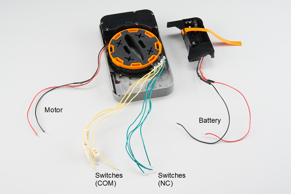
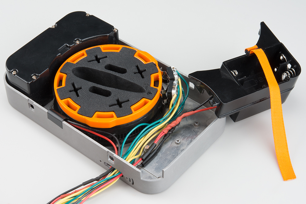
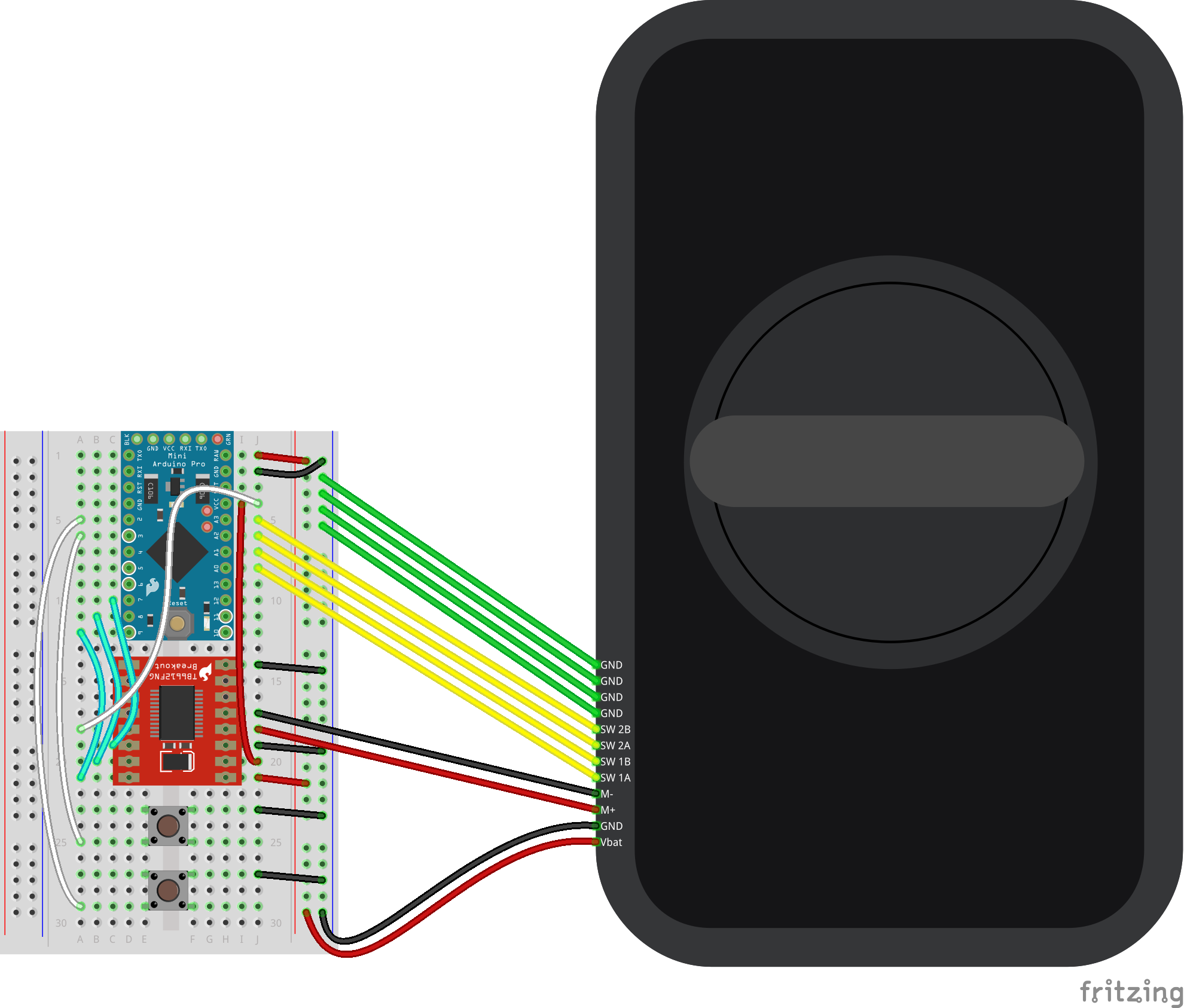
We first want to connect a set of wires to the limit switches, motor, and battery compartment. In the end, we should have something like the picture below. The following steps will show you how to get there.
Connect Wires to the Switches
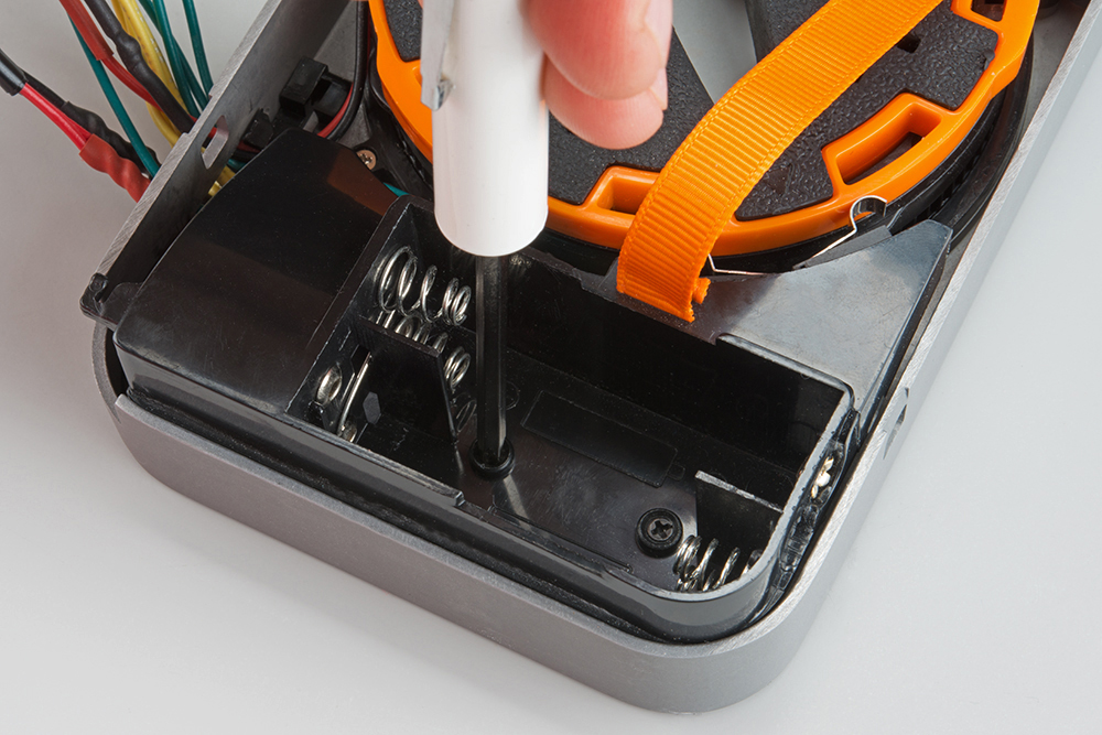
Unscrew the battery holder, and set it aside (if you have not done so already). Examine the limit switches.
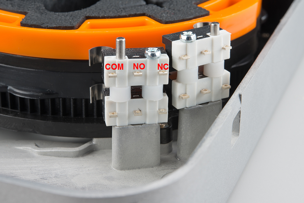
- COM - Common terminal
- NO - Normally open. The COM and NO terminals are connected when the switch is engaged.
- NC - Normally closed. The COM and NC terminals are connected when the switch is not engaged.
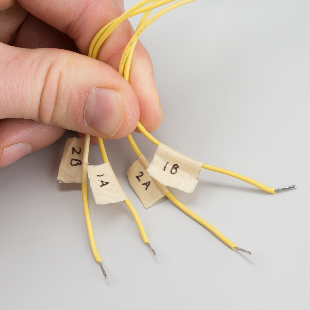
Cut, strip, and tin 8x 6-8 inch wires (I used 4 green and 4 yellow wires). Solder them to the outermost terminals on the limit switches. We will be using the COM and NC terminals.
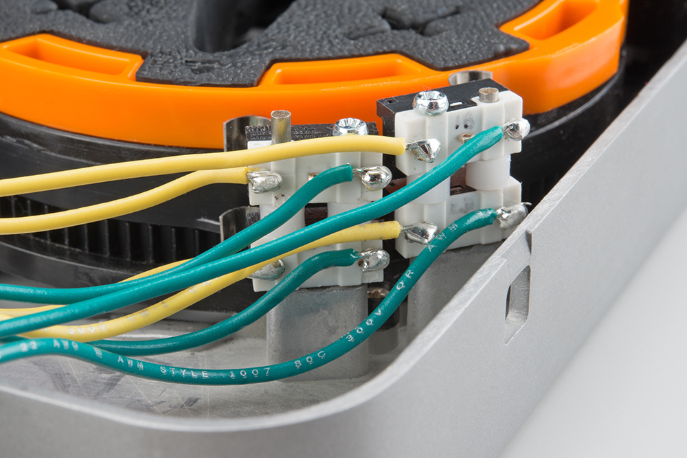
We recommend you label the wires so you know to which switch it is connected. In this instance, I tagged all the yellow (COM) wires with their respective switch (1A, 1B, 2A, 2B). I plan to connect the green wires (NC) all to ground and the yellow wires (COM) to individual Arduino pins.
Extend the Motor Wires
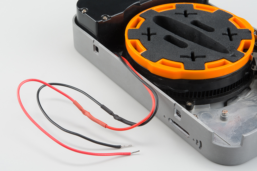
Cut, strip, and tin another 2x 6-8 inch wires for the motor. Use your favorite wire splicing technique (here are some good ones: 1, 2, 3) to connect to the motor wires. I used red and black to keep with the + and - theme.
Extend the Battery Wires
Once again, cut, strip, and tin another set of wires for the batteries. You will need 2x 6-8 inch wires. Use your favorite splicing technique to connect to the battery wires. I used red and black wires to connect to + and -, respectively.

Route Wires out of the Housing
Carefully pull all the wires through the button opening in the housing.
Solder Headers
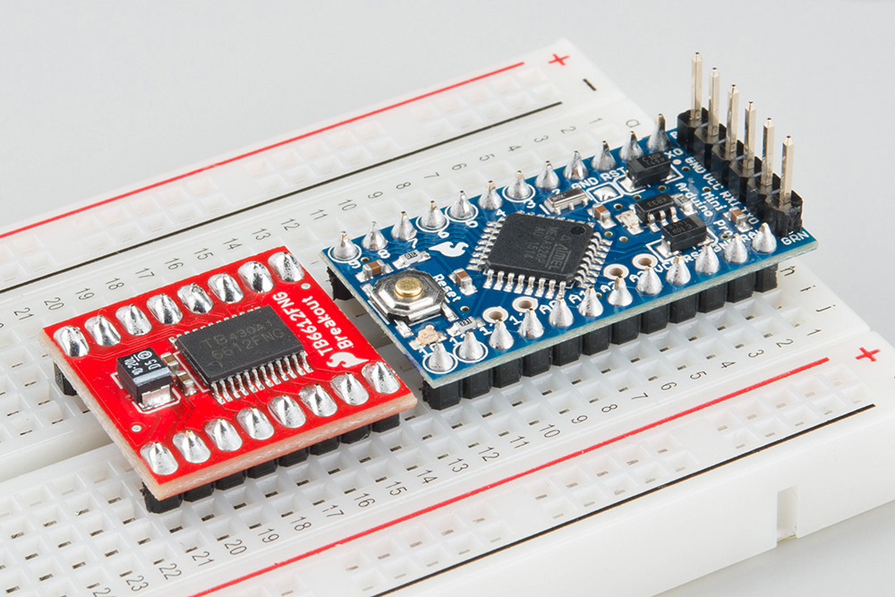
Solder headers onto the Pro Mini and Motor Driver board. Don't forget to add headers to the programming port of the Pro Mini (the part where you attach the FTDI breakout).
Attach Everything to a Breadboard
Attach the Pro Mini, Motor Driver board, and 2 buttons to the breadboard. Connect the wires from the Lockitron to the breadboard and add additional wires as shown.
Replace Battery Holder
Screw the battery holder back in place, making sure that the limit switch wires do not get caught underneath. Do not add batteries at this time.