$13.95
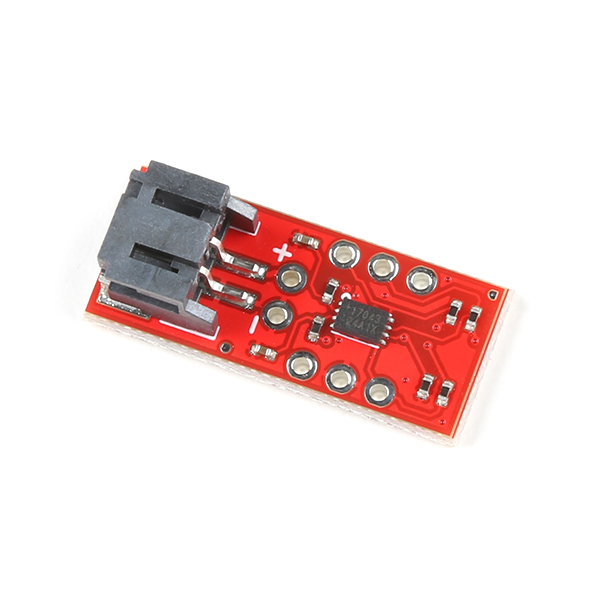
The SparkFun LiPo Fuel Gauge - MAX17043 connects your LiPo battery to your project and uses a sophisticated algorithm to detect the relative state of charge and direct A/D measurement of battery voltage. In other words, it tells your microcontroller how much 'fuel' is left in the tank. The LiPo Fuel Gauge Breakout communicates with your project over I2C and an alert pin also tells you when the charge has dropped below a certain percentage.
To follow along with this tutorial, you will need the following materials at a minimum. You may not need everything though depending on what you have. Add it to your cart, read through the guide, and adjust the cart as necessary. Below is a wishlist of the parts that you need to get started.
You will need a microcontroller with an I2C port when connecting to the LiPo Fuel Gauge. For the scope of this tutorial, we will be focusing on the Arduino Library for the LiPo Fuel Gauge.
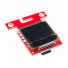
The example code can be used to print the voltage and state of charge of a single cell, LiPo battery using a serial monitor. For those that want to monitor a battery remotely, you can add a display to the setup. Below is the Qwiic Micro OLED breakout that can be used. You can also use a different display. However, you will need to adjust the code to display the readings properly.
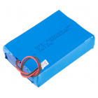
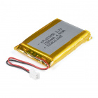
Of course, you will also need a single cell LiPo battery. Below are a few LiPo batteries to choose from in the SparkFun catalog.
Building a circuit using this breakout requires some assembly and soldering. You may already have a few of these items but if not, the tools and hardware below help with that assembly.

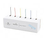
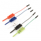
Depending on your setup, you may want to use IC hooks for a temporary connection. However, you will want to solder header pins to connect devices to the plated through holes for a secure connection. Depending on your application, you could use straight headers or right angle headers. Of course, you could also solder wire as well.
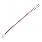
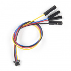
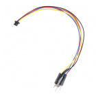
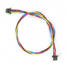
For those that want to take advantage of the Qwiic enabled devices, you'll want to grab a Qwiic cable. Users can cut, strip, and solder half of a cable to easily connect the LiPo Fuel Gauge to a Qwiic-enabled microcontroller. For those that soldered male header pins to the board when prototyping, users can use a Qwiic cable with male pins or female sockets to connect without desoldering the header pins on the board. Note that this causes the board to have a higher height profile than soldering wires straight to the board.
If you aren’t familiar with the following concepts, we also recommend checking out a few of these tutorials before continuing.
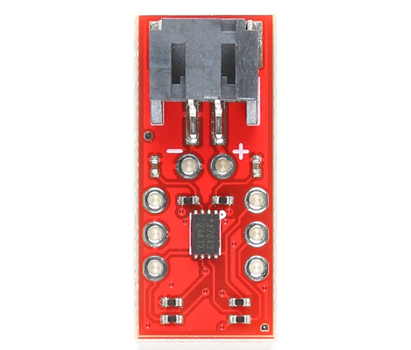
In this section, we will highlight parts of the LiPo Fuel Gauge (MAX17043) breakout board. For users that have a built in fuel gauge (MAX17043/MAX17048) already on your Arduino microcontroller, you can skip this section. The row of 1x3 header pins are arranged in a way so that you can insert the board a standard breadboard.
 |
 |
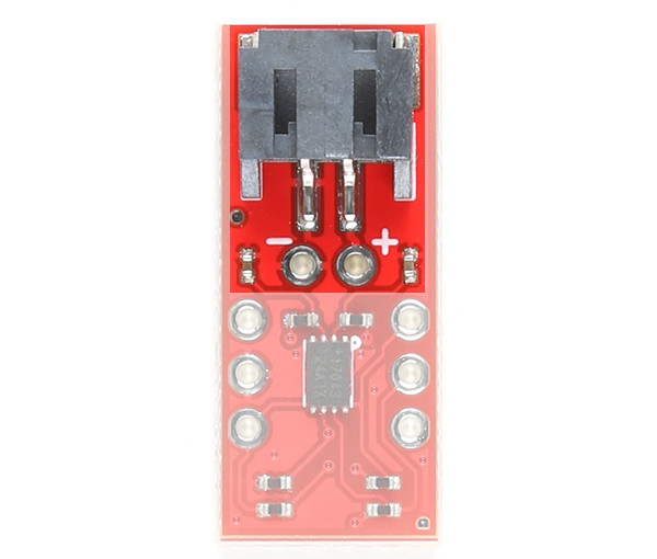
| Top View | Bottom View |
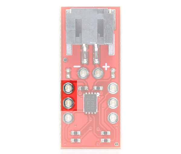
The board includes a 2-pin JST connector to mate with single cell LiPo batteries. We have also broke out the pins to PTHs labeled as + and −. These can be used to solder the LiPo battery wires directly to the board and to your system's VBATT pin. The input voltage range is between 2.5V to 4.5V. Note that the nominal voltage of a single cell LiPo Battery is around 3.7V. Fully charged, the voltage is at around 4.2V. This input also powers the IC and should be connected to your system's power input as well.
 |
 |
| Battery Input Highlighted - Top View |
Battery Input Highlighted - Bottom View |
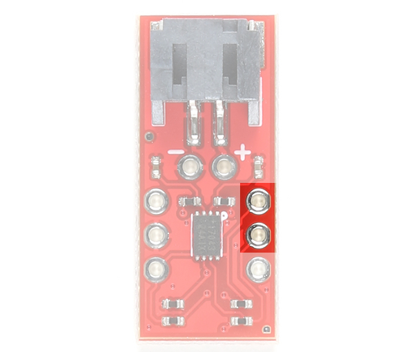
VCC pin is connected to the I2C and alert pull-up resistors. This voltage input pin is different from the battery input pin. The maximum voltage that can be connected to this pin is 5.5V. This is typically 3.3V. If you decide to daisy chain the LiPo Fuel Gauge to Qwiic-enabled devices, we recommend using 3.3V.
 |
 |
| Power Input Highlighted - Top View |
Power Input Highlighted - Bottom View |
The I2C pins are broken out to PTHs. The 7-bit, unshifted address of the MAX17043 is 0x36. The address becomes 0x6C for write and 0x6D for read. There are two 2.2kΩ pull-up resistors connected to the SDA and SCL lines. These lines are connected to the VCC pin.
 |
 |
| I2C Pins Highlighted - Top View |
I2C Pins Highlighted - Bottom View |
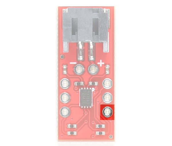
The ALT pin is the alert pin. The datasheet labels this as ALRT but we decided to label it as ALT due to the size of the board. This pin is active low indicating that there is a low state of charge. This pin can be connected to a microcontroller's interrupt pin. This pin can be left unconnected and the status can be viewed though I2C.
 |
 |
| Alert Pin Highlighted - Top View |
Alert Pin Highlighted - Bottom View |
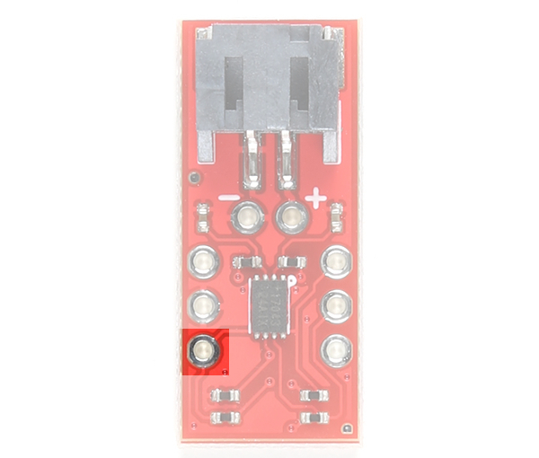
The QST pin is for quick-start input. The datasheet labels this pin as QSTRT but we decided to label it as QST due to the size of the board. This allows users to reset the device through hardware. By default, the pin is connected to ground through a built-in 2.2kΩ resistor as suggested by the datasheet. A rising edge on this pin will initiate a hardware reset. One possible application is connecting this pin to a microcontrollers reset pin should users decide to initiate a hardware reset. A reset can also be initiated through software as well.
 |
 |
| Quick-Start Input Pin Highlighted - Top View |
Quick-Start Input Pin Highlighted - Bottom View |
By default, this 3-pad jumper is closed and located on the bottom of the board. The 2.2kΩ pull-up resistors are attached to the primary I2C bus; if multiple devices are connected to the bus with the pull-up resistors enabled, the parallel equivalent resistance will create too strong of a pull-up for the bus to operate correctly. As a general rule of thumb, disable all but one pair of pull-up resistors if multiple devices are connected to the bus.

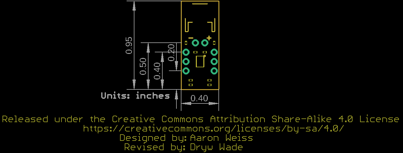
The board is 0.40" x 0.95". To make the board as small as possible, there are no mounting holes included on the board.
Now that we're familiar with the LiPo Fuel Gauge Breakout, let's connect it to a microcontroller and monitor a single cell LiPo battery!
For a permanent connection, we recommend soldering wires (or headers) to the PTHs on the breakout. We chose to use a combination of header pins and wires when prototyping. Of course, you could also solder wires to the breakout board as well. For a temporary connection during prototyping, you can use IC hooks like these.
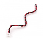
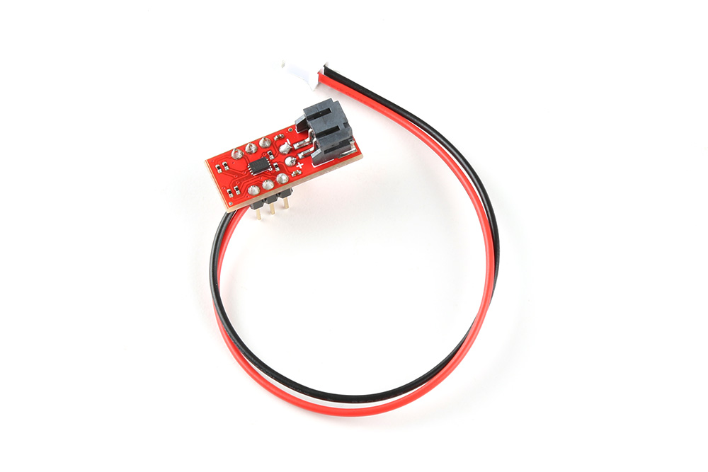
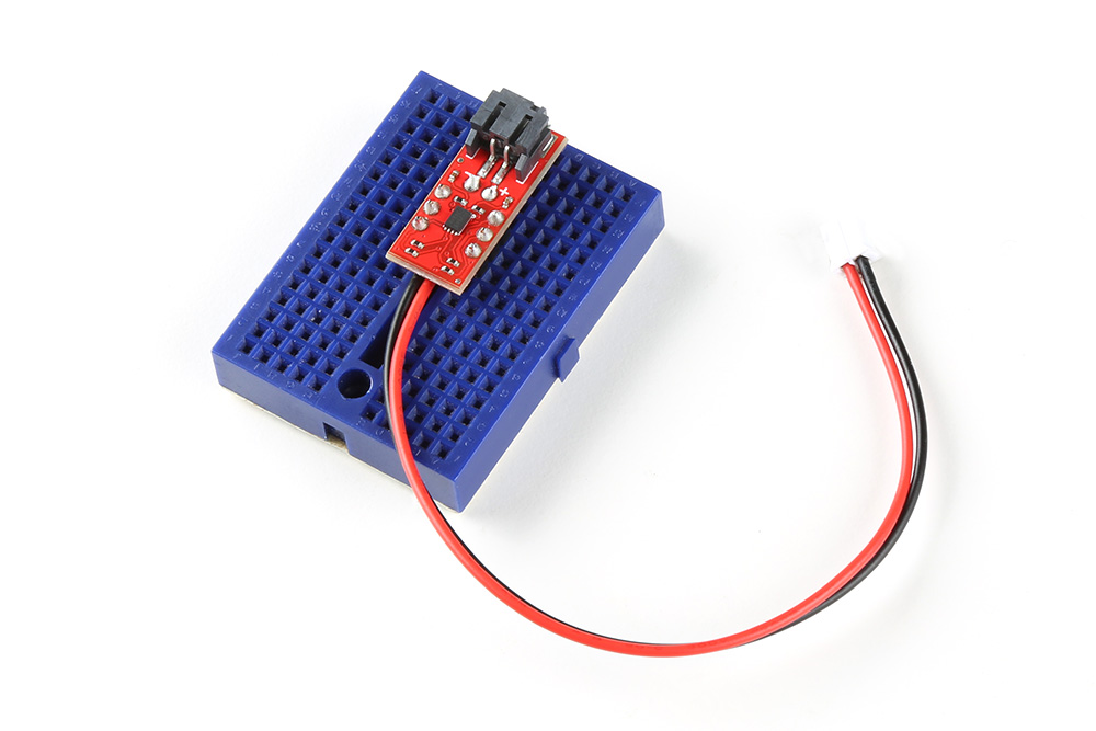
We recommend soldering the header pins and wires on one side. After soldering two rows of 1x3 header pins and a two wire cable, your setup should look like the following image below. We decided to solder the straight header pins and wire all on the top side of the board. Depending on your application, you could solder the straight header pins on the bottom side as well. This will allow you to easily view the silkscreen if you decide to solder on the bottom. Make sure to wire the red wire to the PTH labeled as "+" and the black wire to the PTH labeled as "−".
For users that want to prototype on a breadboard, you could insert the breakout board in the middle of a breadboard. Thanks to the header pin's plastic spacers, the cable can fit between the PCB and the breadboard. The image below shows the breakout board inserted into a mini breadboard. The edge of the board is on the edge of the mini breadboard so that you can disconnect/connect a LiPo battery to the 2-pin JST connector.
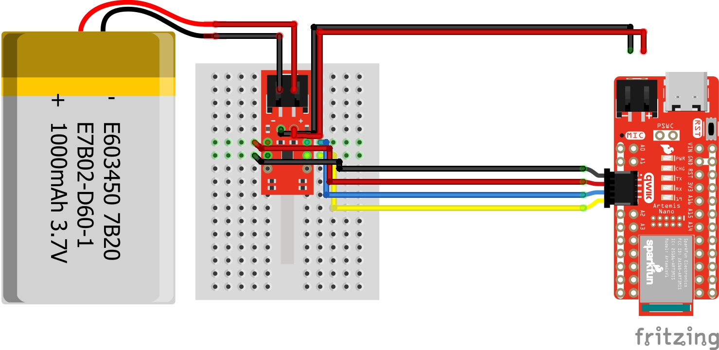
Connect the I2C pins, GND, and Vcc from LiPo Fuel Gauge to your microcontroller. We recommend using 3.3V for Vcc. Insert the battery into the LiPo Fuel Gauge's 2-pin JST connector. Then connect the JST cable that was soldered to your microcontroller's voltage input. In this case, we connected Qwiic cable to the RedBoard Artemis Nano's Qwiic connector and the 2-wire JST cable to the 2-pin JST connector.
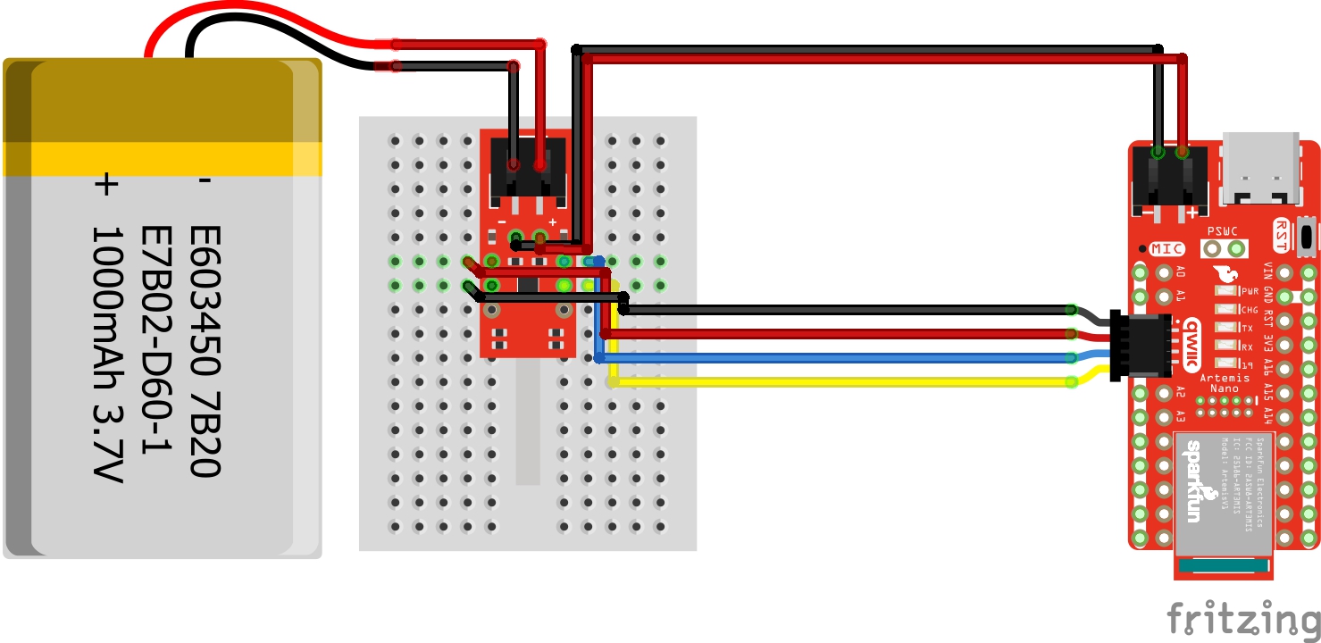
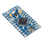
Users can include a LiPo charge circuit to safely charge the LiPo battery without needing to remove the LiPo battery from the LiPo Fuel Gauge. Below is one example that uses the LiPo Charger Plus to charge a single cell LiPo battery while it is also connected to an Arduino Pro Mini 3.3V/8MHz.

As the note indicates in the image, make sure to choose one power source for your Arduino microcontroller to avoid conflicting voltages: either from the LiPo battery or a USB-to-serial converter.
The Fritzing diagram shows male header pins connected to all but the VCC pin on the serial header. When connecting the USB-to-serial converter, this allows users to upload code or view serial data through the Arduino Serial Monitor without needing to worry about conflicting voltages from the FTDI's 3.3V pin.
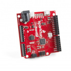
Users can also include a boost circuit when users need a steady 5V input. Below is one example that uses the LiPo Charger/Booster 5V/1A to boost the voltage to 5V for the RedBoard Qwiic. Most microcontrollers usually run at 3.3V so you may not need to worry about boosting it for your Arduino. However, 5V could be used for addressable LEDs, servos, and motors.
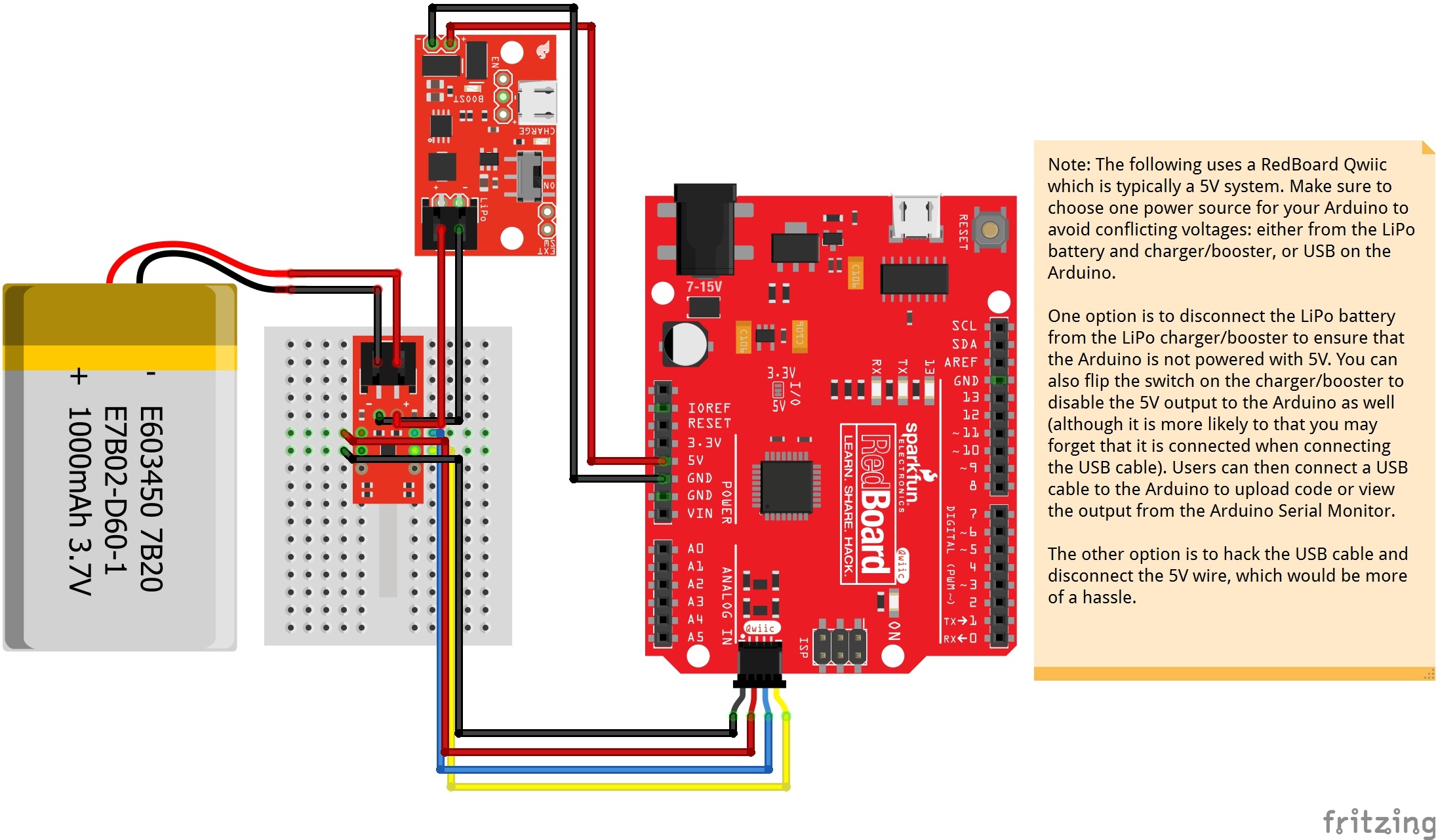
As the note indicates in the image, make sure to choose one power source for your Arduino microcontroller to avoid conflicting voltages: either from the LiPo battery and charger/booster, or USB on the Arduino.
The Fritzing diagram does not show the wires disconnected from the LiPo charger/booster. However, this would be the better option to ensure that the battery is not connected to the RedBoard Qwiic's input power pins. Users could also disconnect the 5V pin from the RedBoard Qwiic's input power pin.
The other option would be to hack the USB cable and disconnect the 5V wire, which would be more of a hassle.
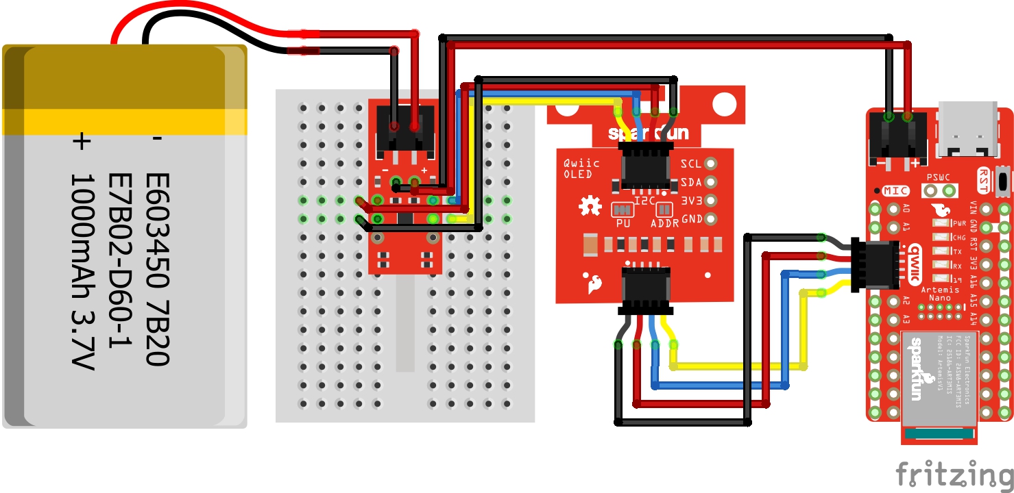
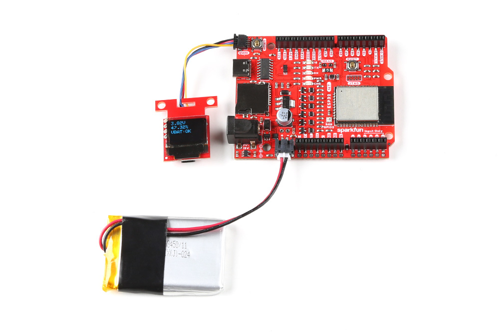
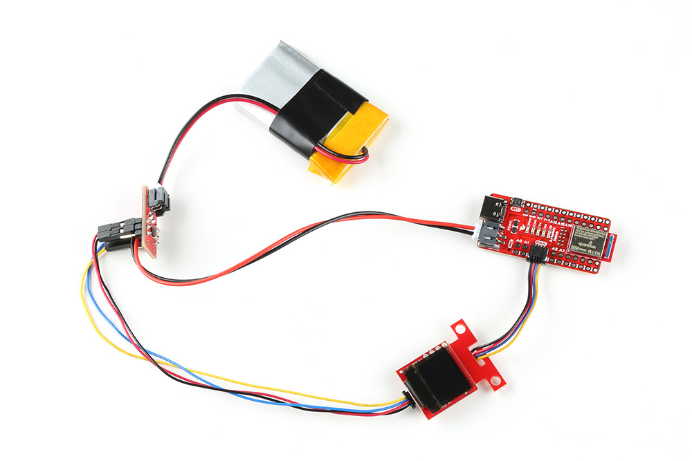
For users that are interested in viewing how much charge a single cell LiPo battery has a available without a computer, users can attach a display to your microcontroller. Below is one example that addes a Qwiic Micro OLED to the first setup. Since you can control the display through I2C, it can be daisy chained using the Qwiic connectors. If you decide to use a different display, you will need to write code to output the values on the display.
The SparkFun MAX1704x Fuel Gauge Arduino Library can be downloaded with the Arduino library manager by searching 'SparkFun MAX1704x Fuel Gauge' or you can grab the zip here from the GitHub repository to manually install.
For users using a Qwiic Micro OLED to display the readings, the SparkFun Qwiic OLED Arduino Library can be downloaded with the Arduino library manager by searching 'SparkFun Qwiic OLED' or you can grab the zip here from the GitHub repository to manually install.
In this example, we will be checking a single cell LiPo battery's voltage and the state of charge using the MAX17043. The output will be sent to the Serial Monitor.
For this example we will use the following parts from the wishlist.
Solder and connect the circuit based on the following diagram as shown earlier. Instead of inserting the LiPo Fuel Gauge in a mini breadboard, you could connect the flexible Qwiic cable with female jumpers to the male break away headers that were soldered on the breakout board. For a more permanent connection, you could also cut the female jumpers, strip the Qwiic cable wires, and solder directly to the breakout board.
From the menu, select the following: File > Examples > SparkFun_MAX1704x_Fuel_Gauge_Arduino_Library > Example1_Simple. If you have not already, select your Board (in this case the RedBoard Artemis Nano), and associated COM port (in this case, COM27). Then hit the upload button.

SFE_MAX1704X lipo; by adding a single line comment (i.e. //. Then remove the single line comment line comment on the respective LiPo Fuel Gauge that you are using.
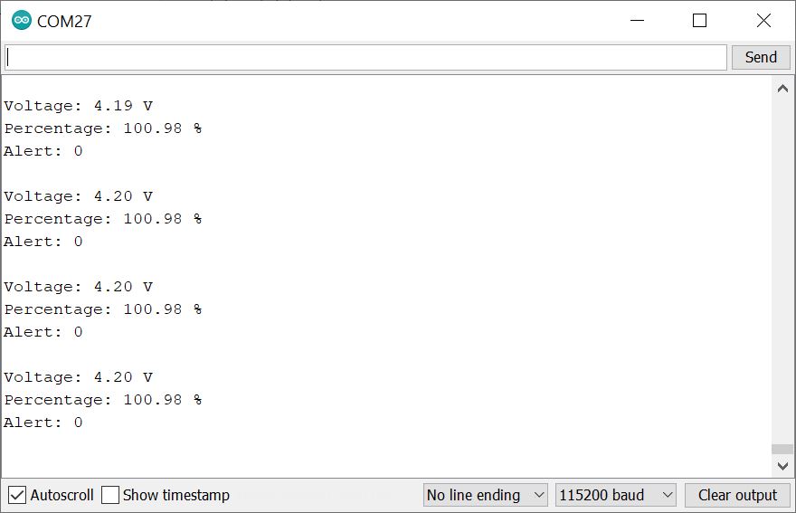
Open the Arduino Serial Monitor and set it to 115200 baud to view the serial output. You should see the voltage, battery percent, and alert flag. In this case, the single cell LiPo battery that was connected to the IC was almost fully charged and at about 4.20V. Since the battery was higher than the threshold that was set, the alert flag was not triggered and remained low.
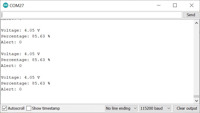
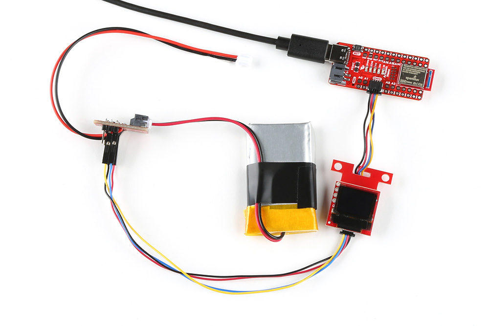
Depending on how your battery is connected to your system, the reading can be a bit misleading. When there is a dedicated LiPo battery charging circuit actively charging the single cell LiPo battery and the MAX1704X initially reads the battery, the values can be higher. Try disconnecting the LiPo battery from the microcontroller's VBATT pin and hitting the reset button on your microcontroller to restart the code. The image below shows both wires disconnected from the RedBoard Artemis Nano's JST connector since we would be using a 2-pin JST jumper wire.
By reopening the Arduino Serial Monitor, you may see a different reading reflecting the current state of the single cell LiPo battery rather than the output voltage of the charge IC. The image below shows actual voltage and remaining charge. You may want to add a display and write additional code as an alternative to connecting to a computer's serial terminal.
In this example, we will be checking a single cell LiPo battery's voltage and the state of charge using the MAX17048. The output will be sent to the Serial Monitor.
For this example we will use the following parts from the wishlist.
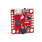
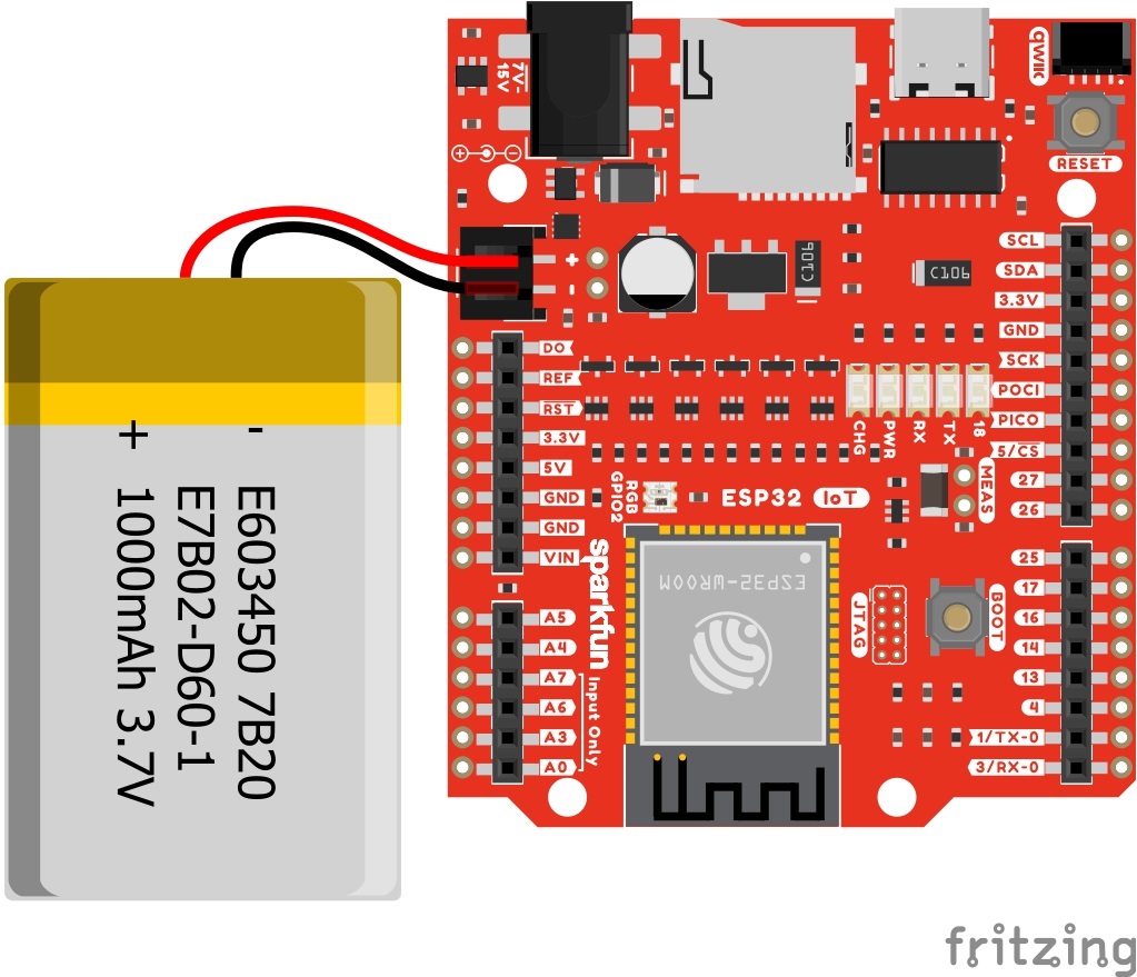
In this case, we did not need to solder anything! The IoT RedBoard - ESP32 has a built in LiPo Fuel Gauge (MAX17048). By simply connecting a LiPo battery to the 2-pin JST connector and uploading code, we should be good to go!
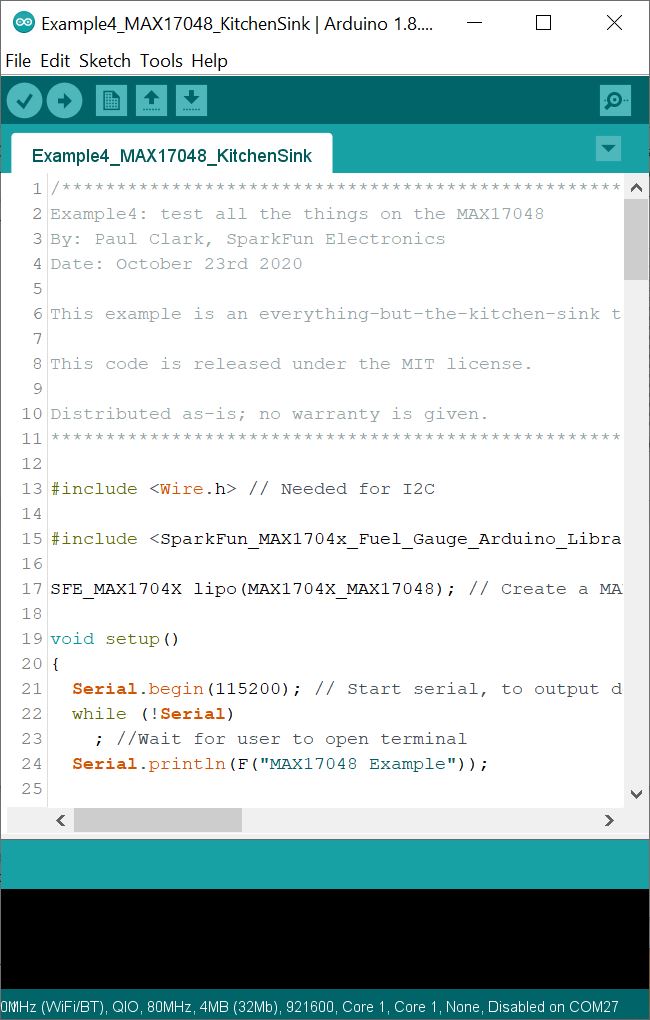
From the menu, select the following: File > Examples > SparkFun_MAX1704x_Fuel_Gauge_Arduino_Library > Example4_MAX17048_KitchenSink. If you have not already, select your Board (in this case the SparkFun ESP32 IoT RedBoard), and associated COM port (in this case COM27). Then hit the upload button.
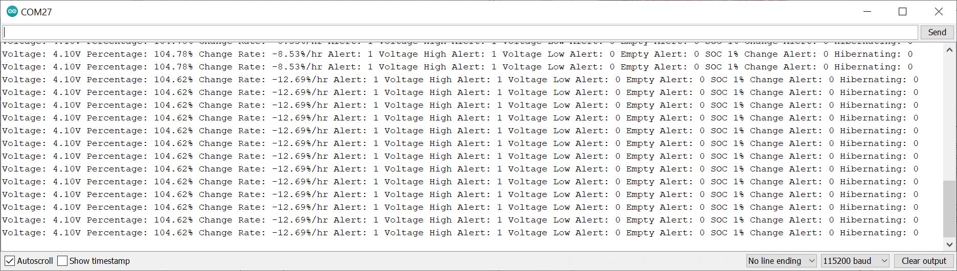
Open the Arduino Serial Monitor and set it to 115200 baud to view the serial output. You should see the voltage, battery percent, alert flag, and several more readings. In this case, the single cell LiPo battery that was connected to the IC was fully charged and at about 4.10V.
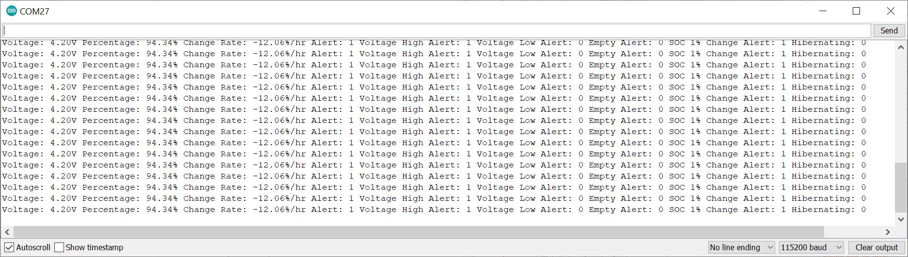
But wait! Remember the previous example? If you looked closely at the circuit of the SparkFun IoT RedBoard - ESP32 Development Board, there is also... you guessed it: a charge circuit built in. Try closing out the Arduino Serial Monitor, disconnecting the USB, and disconnecting the LiPo battery. Then reinsert the LiPo battery, connect the USB cable, and reopen the Arduino Serial Monitor. The IC will recalculate everything. In the image below, the voltage is a bit misleading since the charge IC is charging the LiPo battery and may not be the true representation of the LiPo battery's voltage. The remaining charge was closer to what was expected.
Looking for more examples? Try checking the other examples in the Arduino Library. Example 2 is basically the same as Example 1, however the code was written for Arduino microcontrollers that have a different non-standard Wire and Serial ports. Example 3 is also based on Example but are for users that are using the MAX17044 IC (MAX17044 is configured for a dual-cell 2S pack). You will see the same readings on the Arduino Serial Monitor for both examples.
In this example, we will be checking a single cell LiPo battery's voltage and the state of charge using the MAX17043. The output will be sent to the Serial Monitor and the Qwiic Micro OLED.
For this example we will use the following parts from the wishlist.
Solder and connect the circuit based on the following diagram as shown earlier. Instead of inserting the LiPo Fuel Gauge in a mini breadboard, you could connect the flexible Qwiic cable with female jumpers to the male break away headers that were soldered on the breakout board. For a more permanent connection, you could also cut the female jumpers, strip the Qwiic cable wires, and solder directly to the breakout board. Insert the Qwiic Micro OLED between the LiPo Fuel Gauge and the RedBoard Artemis Nano.
After soldering and connecting the boards together, your setup should look similar to the following.
Depending on the microcontroller that you have and setup, you may want to disconnect the LiPo battery when uploading code and monitoring the LiPo battery through the Arduino Serial Monitor. The values may be misleading due the built in charge circuit that is on the RedBoard Artemis Nano.
Copy and paste following code into your Arduino IDE. If you have not already, select your Board (in this case the RedBoard Artemis Nano), and associated COM port (in this case, COM27). Then hit the upload button.
language:c
/******************************************************************************
  Combined Simple Serial and Qwiic Micro OLED Example
  Modified By: Ho Yun "Bobby" Chan
  SparkFun Electronics
  Date: February 10, 2023
  License: MIT. See license file for more information but you can
  basically do whatever you want with this code.

  This is a combined example of Paul Clark's MAX17043 Fuel Guage
  simple serial example and Kirk Benell's Qwiic OLED Hello
  example. The example reads a single cell LiPo battery's voltage
  and state-of-charge (SOC) using the MAX1704X. The voltage,
  percent remaining (i.e. the SOC), and alert flag are displayed
  as an output on the Qwiic Micro OLED.

  By opening the Arduino Serial Monitor (115200 baud), the example
  will also print the gauge's voltage, state-of-charge (SOC)
  readings, alert status to Serial.

  Feel like supporting open source hardware?
  Buy a board from SparkFun!

  LiPo Fuel Gauge - MAX17043: https://www.sparkfun.com/products/20680
  Qwiic Micro OLED: https://www.sparkfun.com/products/14532

  Distributed as-is; no warranty is given.
******************************************************************************/

#include <Wire.h> // Needed for I2C

//////////LIPO FUEL GAUGE//////////
#include <SparkFun_MAX1704x_Fuel_Gauge_Arduino_Library.h> // Click here to get the library: http://librarymanager/All#SparkFun_MAX1704x_Fuel_Gauge_Arduino_Library

SFE_MAX1704X lipo; // Defaults to the MAX17043

//SFE_MAX1704X lipo(MAX1704X_MAX17043); // Create a MAX17043
//SFE_MAX1704X lipo(MAX1704X_MAX17044); // Create a MAX17044
//SFE_MAX1704X lipo(MAX1704X_MAX17048); // Create a MAX17048
//SFE_MAX1704X lipo(MAX1704X_MAX17049); // Create a MAX17049

double voltage = 0; // Variable to keep track of LiPo voltage
double soc = 0; // Variable to keep track of LiPo state-of-charge (SOC)
bool alert; // Variable to keep track of whether alert has been triggered


//////////QWIIC MICRO OLED//////////
#include <SparkFun_Qwiic_OLED.h> //http://librarymanager/All#SparkFun_Qwiic_Graphic_OLED

// The Qwiic OLED Library supports three different types of SparkFun boards. The demo uses the following
// defines to determine which device is being used. Uncomment the device being used for this demo.

QwiicMicroOLED myOLED;
// QwiicTransparentOLED myOLED;
// QwiicNarrowOLED myOLED;

// Fonts
#include <res/qw_fnt_5x7.h>
//#include <res/qw_fnt_8x16.h>, not used
//#include <res/qw_fnt_31x48.h>, not used
//#include <res/qw_fnt_7segment.h>, not used
//#include <res/qw_fnt_largenum.h>, not used


void setup() {
  Serial.begin(115200); // Start serial, to output debug data
  //while (!Serial)
  //  ; //Wait for user to open terminal
  Serial.println(F("Combined MAX17043 Simple Serial Example & Qwiic OLED Example"));

  Wire.begin();

  lipo.enableDebugging(); // Uncomment this line to enable helpful debug messages on Serial

  // Set up the MAX17043 LiPo fuel gauge:
  if (lipo.begin() == false) // Connect to the MAX17043 using the default wire port
  {
    Serial.println(F("MAX17043 not detected. Please check wiring. Freezing."));
    while (1)
      ;
  }

  // Initalize the OLED device and related graphics system
  if (myOLED.begin() == false)
  {
    Serial.println("Device begin failed. Freezing...");
    while (true)
      ;
  }

  // Quick start restarts the MAX17043 in hopes of getting a more accurate
  // guess for the SOC.
  lipo.quickStart();

  // We can set an interrupt to alert when the battery SoC gets too low.
  // We can alert at anywhere between 1% - 32%:
  lipo.setThreshold(20); // Set alert threshold to 20%.
}// end setup()


void loop() {

  // lipo.getVoltage() returns a voltage value (e.g. 3.93)
  voltage = lipo.getVoltage();

  // lipo.getSOC() returns the estimated state of charge (e.g. 79%)
  soc = lipo.getSOC();

  // lipo.getAlert() clears the alert flag
  // Output: 0 on success, positive integer on fail.
  lipo.clearAlert();
  // lipo.getAlert() returns a 0 or 1 (0=alert not triggered)
  alert = lipo.getAlert();

  myOLED.erase(); //clear display

  //set font type, we'll use a character size of 5x7
  myOLED.setFont(&QW_FONT_5X7);
  //myOLED.setFont(&QW_FONT_8X16);  //not used
  //myOLED.setFont(&QW_FONT_31X48); //not used
  //myOLED.setFont(&QW_FONT_LARGENUM); //not used
  //myOLED.setFont(&QW_FONT_7SEGMENT); //not used

  //Print Voltage
  myOLED.setCursor(0, 0);
  myOLED.print(voltage, 2);
  myOLED.print(F("V"));

  //Print Battery %
  myOLED.setCursor(0, 10);
  myOLED.print(soc, 2);
  myOLED.print(F("%"));

  //Print Alert Status
  myOLED.setCursor(0, 20);
  myOLED.print(F("VBAT:")); //alert pin
  if (alert == HIGH) {
    myOLED.print("LOW"); //Flag was raised, battery is low!!!
  }
  else {

    myOLED.print(F("OK")); //Battery charge is good. 8)
  }

  // There's nothing on the screen yet - Now send the graphics to the device
  myOLED.display();


  // Print the variables to Serial Terminal:
  Serial.print(F("Voltage: "));
  Serial.print(voltage);  // Print the battery voltage
  Serial.println(F(" V"));

  Serial.print(F("Percentage: "));
  Serial.print(soc); // Print the battery state of charge
  Serial.println(F(" %"));

  Serial.print(F("Alert: "));
  Serial.println(alert);
  Serial.println();

  delay(500);
}//end loop()
Disconnect the USB cable from your RedBoard Artemis Nano. Hit the reset button.

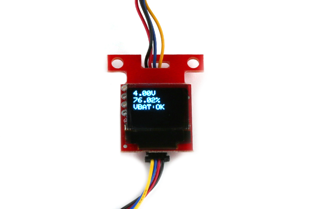
Looking close at the display, you should see the voltage, remaining charge, the alert flag indicating if the battery is low, and a battery meter icon. These values may be different depending on how much charge the LiPo battery has available.
This example is pretty much the same as the previous combined example. However, we will add an additional battery meter icon.
For this example we will use the same parts as the previous combined example's wishlist.
Copy and paste following code into your Arduino IDE.
language:c
/******************************************************************************
  Combined Simple Serial and Qwiic Micro OLED Example
  Modified By: Ho Yun "Bobby" Chan
  SparkFun Electronics
  Date: February 10, 2023
  License: MIT. See license file for more information but you can
  basically do whatever you want with this code.

  This is a combined example of Paul Clark's MAX17043 Fuel Guage
  simple serial example, Kirk Benell's Qwiic OLED Hello example,
  and Nathan Seidle's RTK Display Test Sketch. The example reads a
  single cell LiPo battery's voltage and state-of-charge (SOC)
  using the MAX1704X. The voltage, percent remaining (i.e. the
  SOC), and alert flag are displayed as an output on the Qwiic
  Micro OLED. A graphic of a LiPo battery's remaining charge is
  displayed on the Qwiic Micro OLED as well.

  By opening the Arduino Serial Monitor (115200 baud), the example
  will also print the gauge's voltage, state-of-charge (SOC)
  readings, alert status to Serial.

  Feel like supporting open source hardware?
  Buy a board from SparkFun!

  LiPo Fuel Gauge - MAX17043 : https://www.sparkfun.com/products/20680
  Qwiic Micro OLED: https://www.sparkfun.com/products/14532

  Distributed as-is; no warranty is given.
******************************************************************************/

#include <Wire.h> // Needed for I2C


//////////LIPO FUEL GAUGE//////////
#include <SparkFun_MAX1704x_Fuel_Gauge_Arduino_Library.h> // Click here to get the library: http://librarymanager/All#SparkFun_MAX1704x_Fuel_Gauge_Arduino_Library

SFE_MAX1704X lipo; // Defaults to the MAX17043

//SFE_MAX1704X lipo(MAX1704X_MAX17043); // Create a MAX17043
//SFE_MAX1704X lipo(MAX1704X_MAX17044); // Create a MAX17044
//SFE_MAX1704X lipo(MAX1704X_MAX17048); // Create a MAX17048
//SFE_MAX1704X lipo(MAX1704X_MAX17049); // Create a MAX17049

double voltage = 0; // Variable to keep track of LiPo voltage
double soc = 0; // Variable to keep track of LiPo state-of-charge (SOC)
bool alert; // Variable to keep track of whether alert has been triggered


//////////QWIIC MICRO OLED//////////
#include <SparkFun_Qwiic_OLED.h> //http://librarymanager/All#SparkFun_Qwiic_Graphic_OLED
#include "icons.h"

// The Qwiic OLED Library supports three different types of SparkFun boards. The demo uses the following
// defines to determine which device is being used. Uncomment the device being used for this demo.
QwiicMicroOLED myOLED;
// QwiicTransparentOLED myOLED;
// QwiicNarrowOLED myOLED;

// Fonts
#include <res/qw_fnt_5x7.h>
//#include <res/qw_fnt_8x16.h>, not used
//#include <res/qw_fnt_31x48.h>, not used
//#include <res/qw_fnt_7segment.h>, not used
//#include <res/qw_fnt_largenum.h>, not used


void setup() {
  Serial.begin(115200); // Start serial, to output debug data
  //while (!Serial)
  //  ; //Wait for user to open terminal
  Serial.println(F("Combined MAX17043 Example & Qwiic OLED Example"));

  Wire.begin();

  lipo.enableDebugging(); // Uncomment this line to enable helpful debug messages on Serial

  // Set up the MAX17043 LiPo fuel gauge:
  if (lipo.begin() == false) // Connect to the MAX17043 using the default wire port
  {
    Serial.println(F("MAX17043 not detected. Please check wiring. Freezing."));
    while (1)
      ;
  }

  // Initalize the OLED device and related graphics system
  if (myOLED.begin() == false)
  {
    Serial.println(F("Device begin failed. Freezing..."));
    while (true)
      ;
  }

  // Quick start restarts the MAX17043 in hopes of getting a more accurate
  // guess for the SOC.
  lipo.quickStart();

  // We can set an interrupt to alert when the battery SoC gets too low.
  // We can alert at anywhere between 1% - 32%:
  lipo.setThreshold(20); // Set alert threshold to 20%.
}

void loop() {

  // lipo.getVoltage() returns a voltage value (e.g. 3.93)
  voltage = lipo.getVoltage();

  // lipo.getSOC() returns the estimated state of charge (e.g. 79%)
  soc = lipo.getSOC();

  // lipo.getAlert() clears the alert flag
  // Output: 0 on success, positive integer on fail.
  lipo.clearAlert();
  // lipo.getAlert() returns a 0 or 1 (0=alert not triggered)
  alert = lipo.getAlert();

  myOLED.erase(); //clear display

  //set font type, we'll use a character size of 5x7
  myOLED.setFont(&QW_FONT_5X7);
  //myOLED.setFont(&QW_FONT_8X16); //not used
  //myOLED.setFont(&QW_FONT_31X48); //not used
  //myOLED.setFont(&QW_FONT_LARGENUM); //not used
  //myOLED.setFont(&QW_FONT_7SEGMENT); //not used

  // "Print" Voltage
  myOLED.setCursor(0, 0);
  myOLED.print(voltage, 2);
  myOLED.print(F("V"));

  // "Print" Battery %
  myOLED.setCursor(0, 10);
  myOLED.print(soc, 2);
  myOLED.print(F("%"));

  // "Print" Alert Status
  myOLED.setCursor(0, 20);
  myOLED.print(F("VBAT:")); //alert pin
  if (alert == HIGH) {
    myOLED.print(F("LOW")); //Flag was raised, battery is low!!!
  }
  else {

    myOLED.print(F("OK")); //Battery charge is good. 8)
  }

  if (soc >= 50.00) {
    //Battery Level 50-100%
    displayBitmap(0, 30, Battery_2_Width, Battery_2_Height, Battery_3);
  }
  else if (20.00 <= soc < 50.00) {
    //Battery Level 20-50%
    displayBitmap(0, 30, Battery_2_Width, Battery_2_Height, Battery_2);
  }
  else if (10.00 <= soc < 20.00) {
    //Battery Level 10%-20%
    displayBitmap(0, 30, Battery_2_Width, Battery_2_Height, Battery_1);
  }
  else {
    //Battery Level <10%
    displayBitmap(0, 30, Battery_2_Width, Battery_2_Height, Battery_0);
  }


  // There's nothing on the screen yet - Now send the graphics to the device
  myOLED.display();


  // Print the variables to Serial Terminal:
  Serial.print(F("Voltage: "));
  Serial.print(voltage);  // Print the battery voltage
  Serial.println(" V");

  Serial.print(F("Percentage: "));
  Serial.print(soc); // Print the battery state of charge
  Serial.println(" %");

  Serial.print(F("Alert: "));
  Serial.println(alert);
  Serial.println();

  delay(500);
}


//Wrapper to avoid needing to pass width/height data twice
void displayBitmap(uint8_t x, uint8_t y, uint8_t imageWidth, uint8_t imageHeight, uint8_t *imageData) {
  myOLED.bitmap(x, y, x + imageWidth, y + imageHeight, imageData, imageWidth, imageHeight);
}
To keep track of the icons that we create, we are going to create a header file with the *.ino. This is useful when writing code for big projects that involve a lot of components (e.g. RTK Express, RTK Express Plus, RTK Facet, RTK Facet L-Band, etc.). Click on the icon to create a new tab. We will name this icons.h.

Copy and paste the following code into tab.
language:c
uint8_t Battery_3 [] = {
0xFF, 0x01, 0xFD, 0xFD, 0xFD, 0x01, 0x01, 0xFD, 0xFD, 0xFD, 0x01, 0x01, 0xFD, 0xFD, 0xFD, 0x01,
0x0F, 0x08, 0xF8, 0x0F, 0x08, 0x0B, 0x0B, 0x0B, 0x08, 0x08, 0x0B, 0x0B, 0x0B, 0x08, 0x08, 0x0B,
0x0B, 0x0B, 0x08, 0x0F, 0x01, 0x01,
};
int Battery_3_Height = 12;
int Battery_3_Width = 19;

uint8_t Battery_2 [] = {
0xFF, 0x01, 0xFD, 0xFD, 0xFD, 0x01, 0x01, 0xFD, 0xFD, 0xFD, 0x01, 0x01, 0x01, 0x01, 0x01, 0x01,
0x0F, 0x08, 0xF8, 0x0F, 0x08, 0x0B, 0x0B, 0x0B, 0x08, 0x08, 0x0B, 0x0B, 0x0B, 0x08, 0x08, 0x08,
0x08, 0x08, 0x08, 0x0F, 0x01, 0x01,
};
int Battery_2_Height = 12;
int Battery_2_Width = 19;

uint8_t Battery_1 [] = {
0xFF, 0x01, 0xFD, 0xFD, 0xFD, 0x01, 0x01, 0x01, 0x01, 0x01, 0x01, 0x01, 0x01, 0x01, 0x01, 0x01,
0x0F, 0x08, 0xF8, 0x0F, 0x08, 0x0B, 0x0B, 0x0B, 0x08, 0x08, 0x08, 0x08, 0x08, 0x08, 0x08, 0x08,
0x08, 0x08, 0x08, 0x0F, 0x01, 0x01,
};
int Battery_1_Height = 12;
int Battery_1_Width = 19;

uint8_t Battery_0 [] = {
0xFF, 0x01, 0x01, 0x01, 0x01, 0x01, 0x01, 0x01, 0x01, 0x01, 0x01, 0x01, 0x01, 0x01, 0x01, 0x01,
0x0F, 0x08, 0xF8, 0x0F, 0x08, 0x08, 0x08, 0x08, 0x08, 0x08, 0x08, 0x08, 0x08, 0x08, 0x08, 0x08,
0x08, 0x08, 0x08, 0x0F, 0x01, 0x01,
};
int Battery_0_Height = 12;
int Battery_0_Width = 19;
If you have not already, select your Board (in this case the RedBoard Artemis Nano), and associated COM port (in this case, COM27). Then hit the upload button. Disconnect the USB cable from your RedBoard Artemis Nano. Hit the reset button.
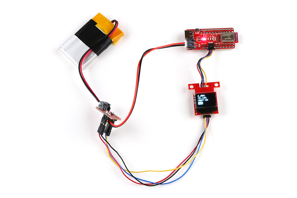
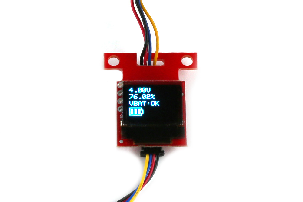
Looking close at the display, you should see the voltage, remaining charge, the alert flag indicating if the battery is low, and a battery meter icon. These values may be different depending on how much charge the LiPo battery has available!

Now that you've successfully got your LiPo Fuel Gauge (MAX17043) up and running, it's time to incorporate it into your own project! For more information, check out the resources below:
Need some inspiration for your next project? Check out some of these related tutorials. Looking for an alternative solution to using a display? Try using an RGB LED to display the remaining charge.
Or check out some of these blog posts for ideas using LiPo fuel gauges.
learn.sparkfun.com | CC BY-SA 3.0 | SparkFun Electronics | Niwot, Colorado