I2S Audio Breakout Hookup Guide
 Alex the Giant
 Hardware Overview
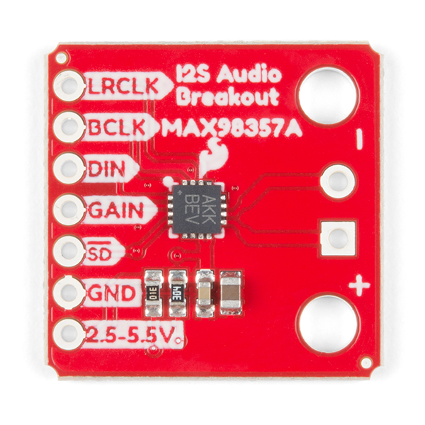
The I2S audio breakout converts the digital audio signals using the I2S standard to an analog signal and amplifies the signal using a class D amplifier. The board can be configured to output only the left channel, right channel, or both. For more information about how to configure the board, refer to the Jumper Selection section below.
Board Specs
| Parameter | Description |
|---|---|
| Supply Voltage Range | 2.5V - 5.5V. |
| Output Power | 3.2W into 4Ω at 5V. |
| Output Channel Selection | Left, Right, or Left/2 + Right/2 (Default). |
| Sample Rate | 8kHz - 96kHz. |
| Sample Resolution | 16/32 bit. |
| Quiescent Current | 2.4mA. |
| Additional Features | Filterless Class D outputs, no MCLK required, click and pop reduction, short-circuit and thermal protection. |
Pin Descriptions
The SparkFun I2S audio breakout board is fairly simple, requiring only a few pin connections to get the board working.
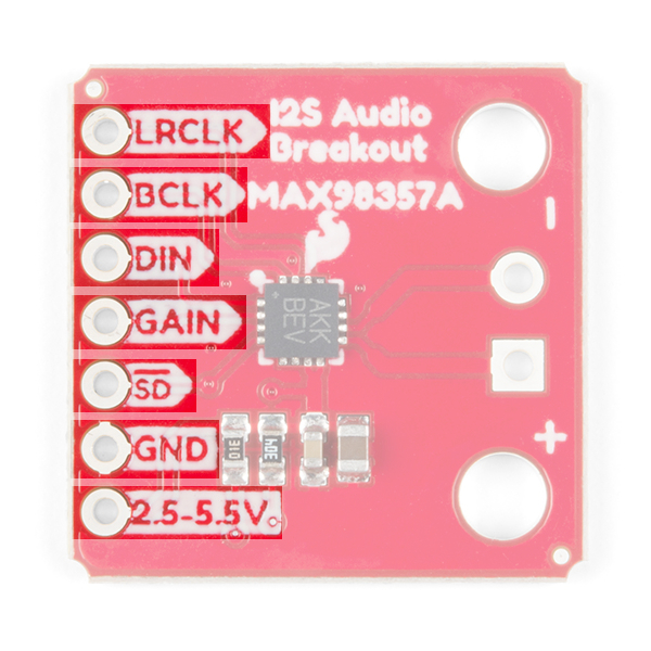
Inputs
| Pin Label | Description |
|---|---|
| LRCLK | Frame clock (left/right clock) input. |
| BCLK | Bit clock input. |
| DIN | Serial data input. |
| GAIN | Gain setting. Can be set to +3/6/9/12/15dB. Set to +9dB by default. |
| SD | Shutdown and channel select. Pull low to shutdown, or use the jumpers to select the channel output (see jumper selection for more information). |
| GND | Connect to ground |
| VDD | Power input. Must be between 2.5 and 5.5VDC. |
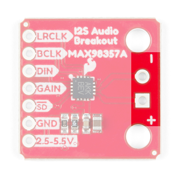
Outputs
The output is where you'll connect your speaker.
| Pin Label | Description |
|---|---|
| + | Positive speaker output. |
| - | Negative speaker output. |
Speaker wire can either be soldered directly to the output pads, but if screw terminals are more your style, you can use our 3.5mm screw terminals.
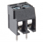
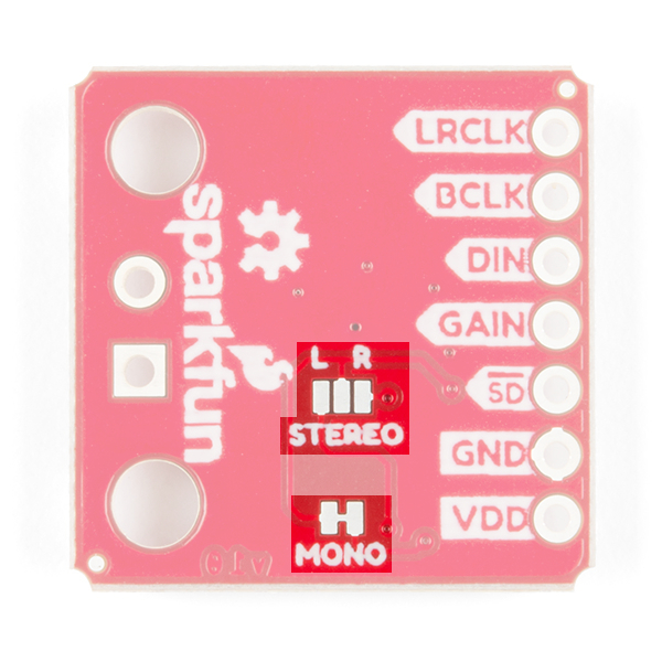
Jumper Selection
By default the board is configured in "mono" operation, meaning the left and right signals are combined together to drive a single speaker.
If you want a separate speaker for the left and right audio channels you'll first need to cut the mono jumper as pictured below.
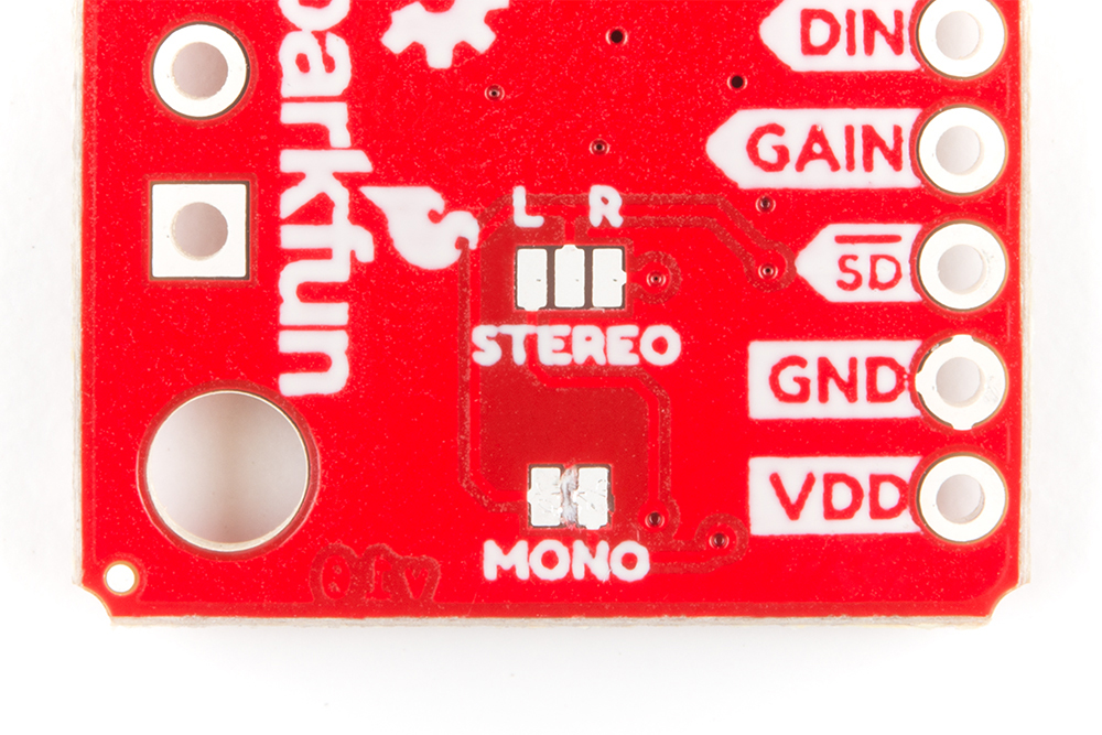
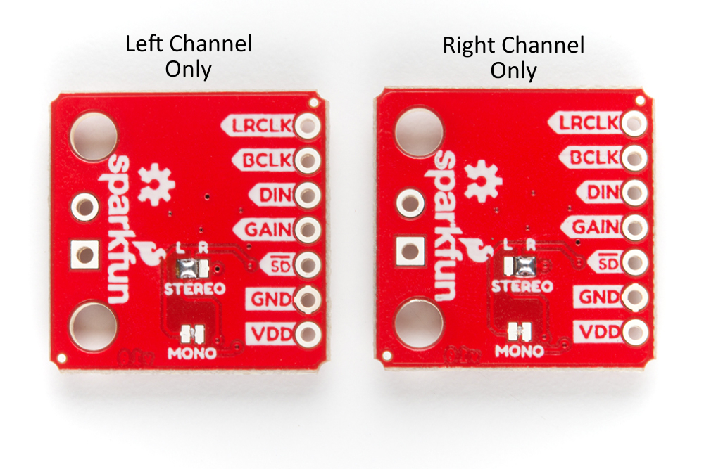
To configure the board to respond to a specific audio channel, you'll need to close the stereo jumper as shown below.
Gain Selection
In addition to being able to select the audio channel output, the gain can also be configured in a few ways. The gain of the amplifier can be configured from as low as +3dB to as high as +15dB. While the channel selection can be configured on board, the gain however is controlled externally using the gain pin. By default, the board is configured for +9dB, but can be changed using the table below.
| Gain (dB) | Gain Pin Connection |
|---|---|
| 15 | Connected to GND through a 100kΩ resistor. |
| 12 | Connected to GND. |
| 9 | Unconnected (Default). |
| 6 | Connected to VDD. |
| 3 | Connected to VDD through a 100kΩ resistor. |