How to Use a Breadboard
 M-Short,
  Joel_E_B
Anatomy of a Breadboard
The best way to explain how a breadboard works is to take it apart and see what’s inside. Using a smaller breadboard it’s easier to see just how they function.
Terminal Strips
Here we have a breadboard where the adhesive backing has been removed. You can see lots of horizontal rows of metal strips on the bottom of the breadboard.
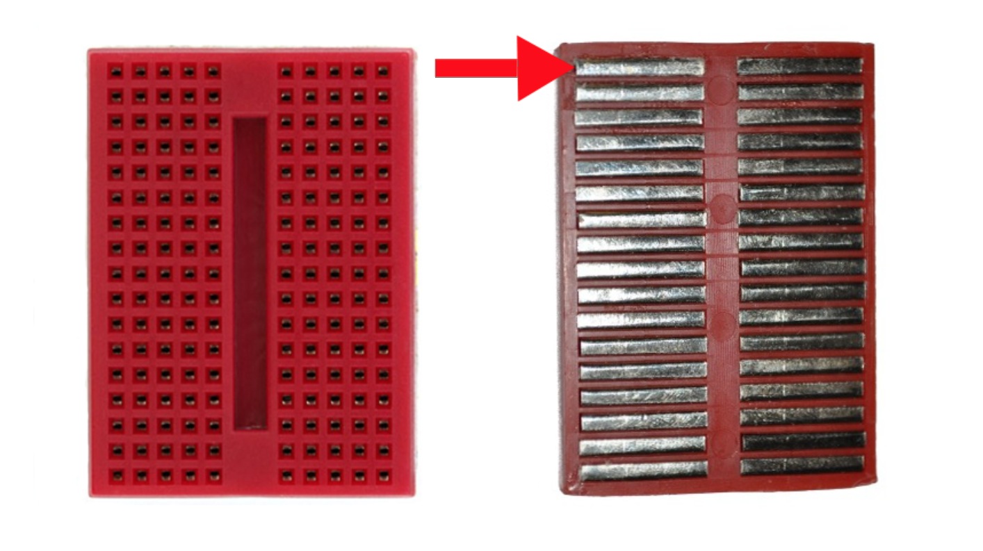
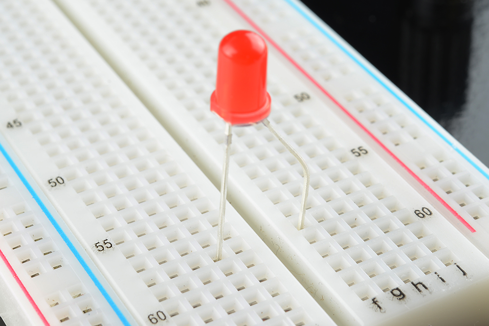
The tops of the metal rows have little clips that hide under the plastic holes. Each metal strip and socket is spaced with a standard pitch of 0.1" (2.54mm). These clips allow you to stick a wire or the leg of a component into the exposed holes on a breadboard, which then hold it in place.
Once inserted that component will be electrically connected to anything else placed in that row. This is because the metal rows are conductive and allow current to flow from any point in that strip.
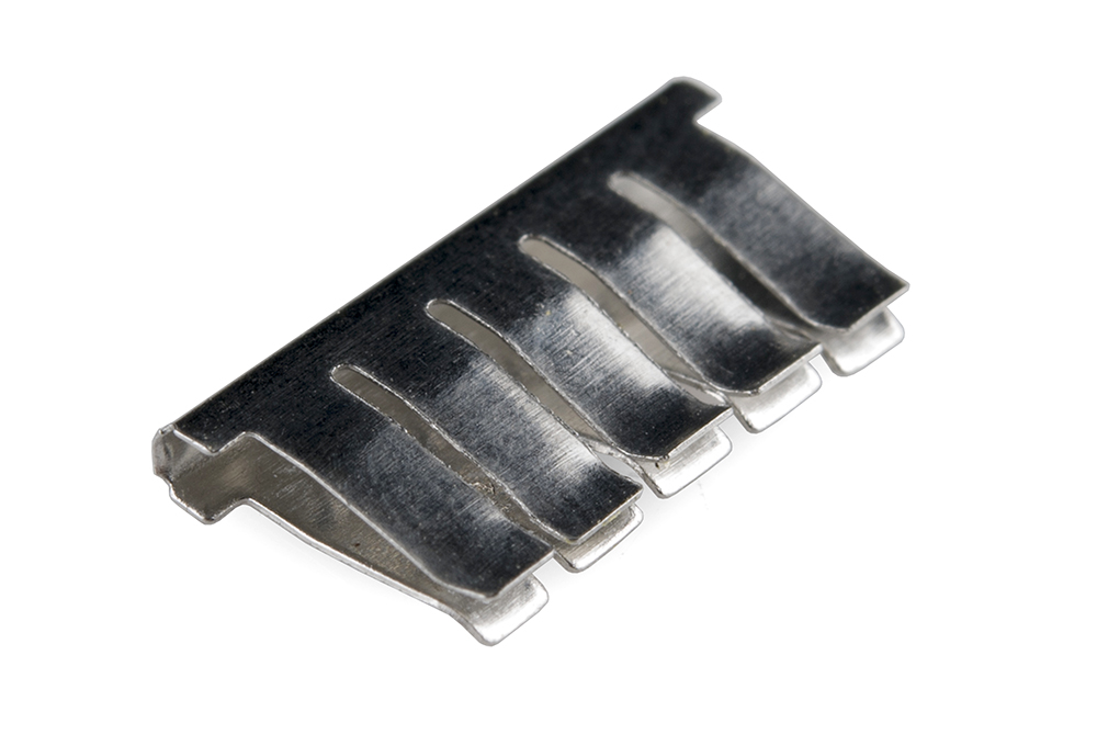
Notice that there are only five clips on this strip. This is typical on almost all breadboards. Thus, you can only have up to five components connected in one particular section of the breadboard. The row has ten holes, so why can you only connect five components? You’ll also notice that each horizontal row is separated by a ravine, or crevasse, in the middle of the breadboard. This ravine isolates both sides of a given row from one another, and they are not electrically connected. We’ll discuss the purpose of this in just a bit, but, for now, just know that each side of a given row is disconnected from the other, leaving you with five spots for components on either side.
Power Rails
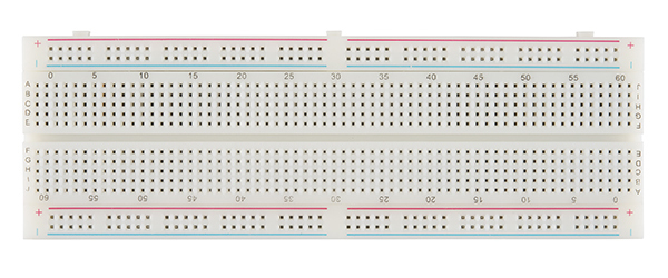
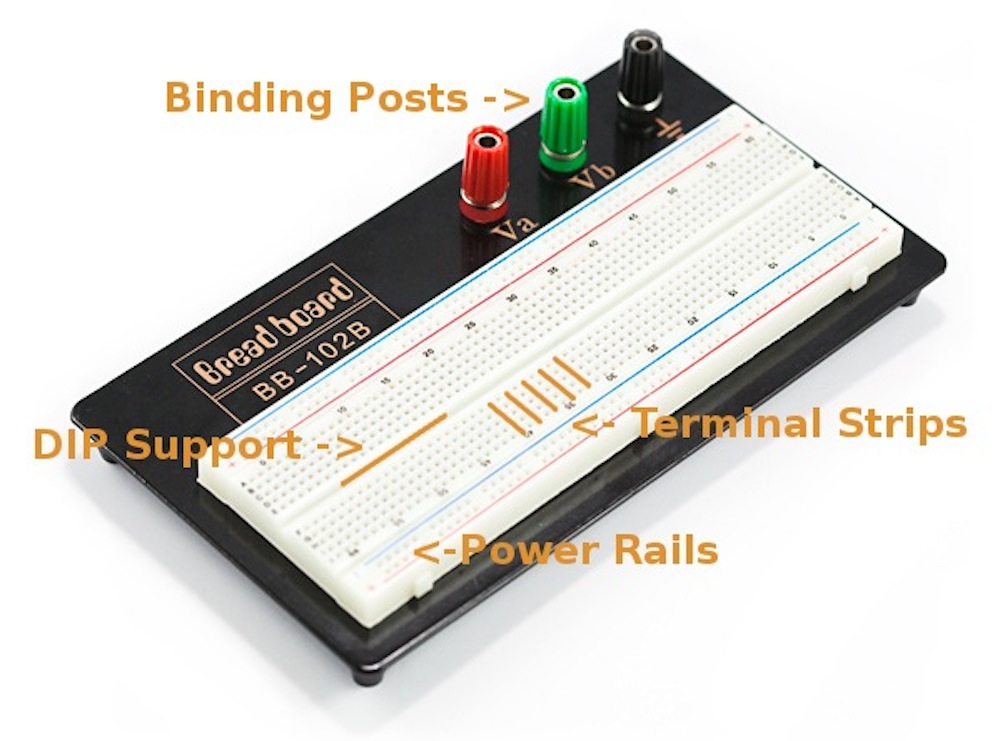
Now that we’ve seen how the connections in a breadboard are made, let’s look at a larger, more typical breadboard. Aside from horizontal rows, breadboards usually have what are called power rails that run vertically along the sides.
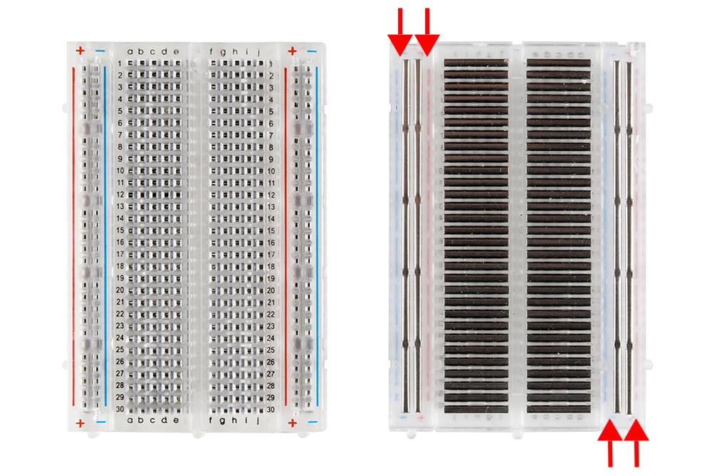
These power rails are metal strips that are identical to the ones that run horizontally, except they are, typically*, all connected. When building a circuit, you tend to need power in lots of different places. The power rails give you lots of easy access to power wherever you need it in your circuit. Usually they will be labeled with a ‘+’ and a ‘-’ and have a red and blue or black stripe, to indicate the positive and negative side.
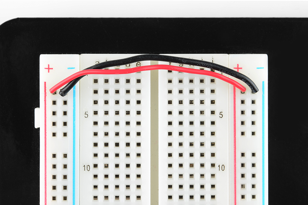
It is important to be aware that the power rails on either side are not connected, so if you want the same power source on both sides, you will need to connect the two sides with some jumper wires. Keep in mind that the markings are there just as a reference. There is no rule that says you have to plug power into the '+' rail and ground into the '-'rail, though it's good practice to keep everything in order.
DIP Support
Earlier we mentioned the ravine that isolates the two sides of a breadboard. This ravine serves a very important purpose. Many integrated circuits, often referred to as ICs or, simply, chips, are manufactured specifically to fit onto breadboards. In order to minimize the amount of space they take up on the breadboard, they come in what is known as a Dual in-line Package, or DIP.
These DIP chips (salsa anyone?) have legs that come out of both sides and fit perfectly over that ravine. Since each leg on the IC is unique, we don’t want both sides to be connected to each other. That is where the separation in the middle of the board comes in handy. Thus, we can connect components to each side of the IC without interfering with the functionality of the leg on the opposite side.

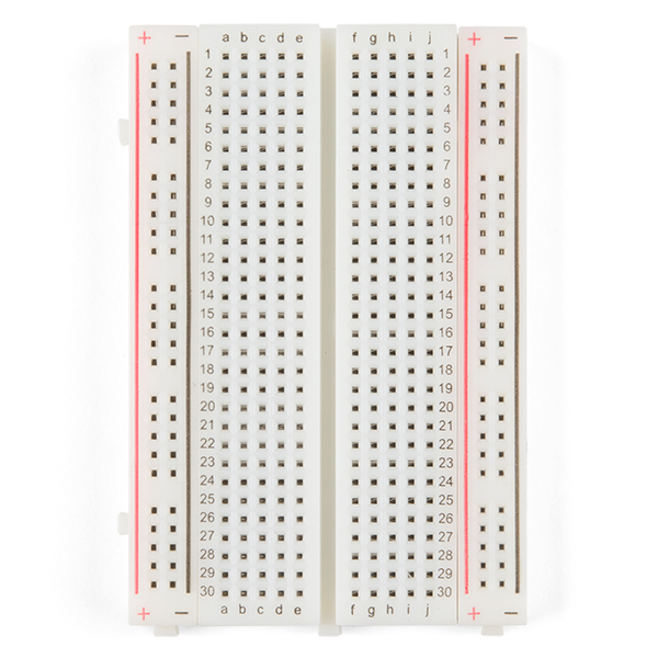
Rows and Columns
You may have noticed that many breadboards have numbers and letters marked on various rows and columns. These don't serve any purpose other than to help guide you when building your circuit. Circuits can get complicated quickly, and all it takes is one misplaced leg of a component to make the entire circuit malfunction or not work at all. If you know the row number of the connection you are trying to make, it makes it much simpler to plug a wire into that number rather than eyeballing it.
These are also helpful when using instruction booklets, such as the one found in the SparkFun Inventor’s Kit. Many books and guides have circuit diagrams for you to follow along while building your circuit. Just remember that the circuit you’re building doesn’t have to be in the exact same location on the breadboard as the one in the book. In fact, it doesn’t even have to look similar. As long as all the electrical connections are being made, you can build your circuit any way you’d like!
Binding Posts
Some breadboards come on a platform that has binding posts attached to it. These posts allow you to connect all kinds of different power sources to your breadboard. We'll cover these more in the next section.
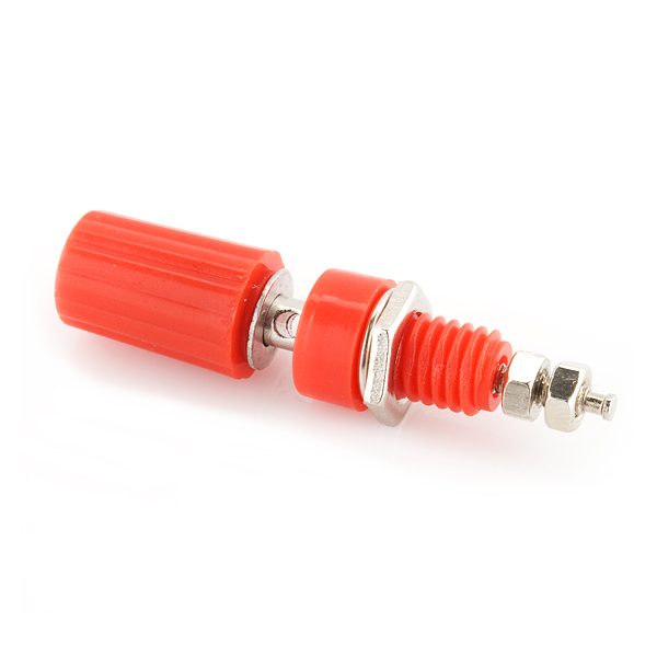 |
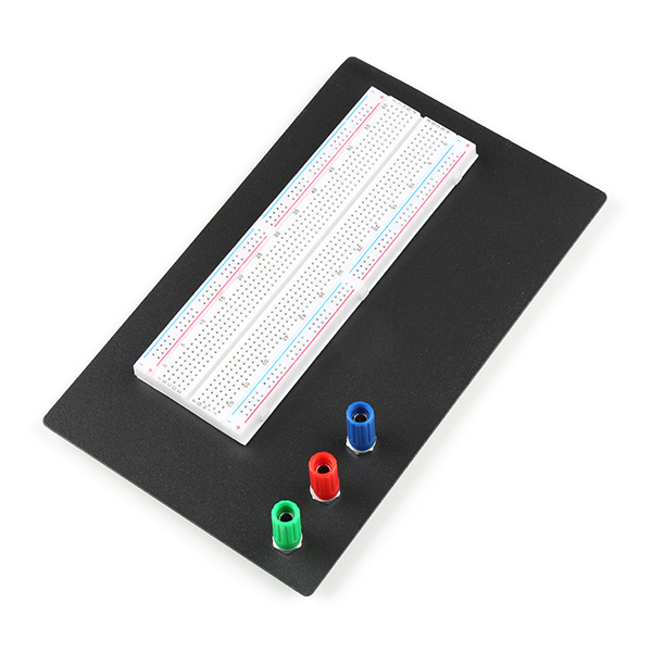 |
| Binding Post for Banana Cables and Wires | Binding Posts on Classic Breadboard |
Other Features
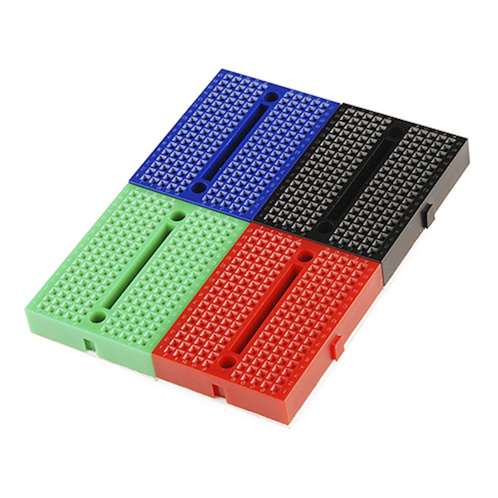
When building your circuit, you are not confined to stay on just one breadboard. Some circuits will require a lot more space. Many breadboards have little nubbins and slots on the sides, and some even have them on the tops and bottoms. These allow you to connect multiple breadboards together to form the ultimate prototyping surface.
Some breadboards also have an adhesive backing that allow you to stick them to many different surfaces. These can come in handy if you want to attach your breadboard to the inside on an enclosure or other project case.