How to Build a Remote Kill Switch
 Nate
Nate 
Vehicle Control Unit
The Vehicle Control Unit (VCU) sits between the motor controller and the motor. The VCU only connects the motor to power if the Remote Control Unit (RCU) is powered up and transmitting the ‘User pressed the green button, go for it’ signal.
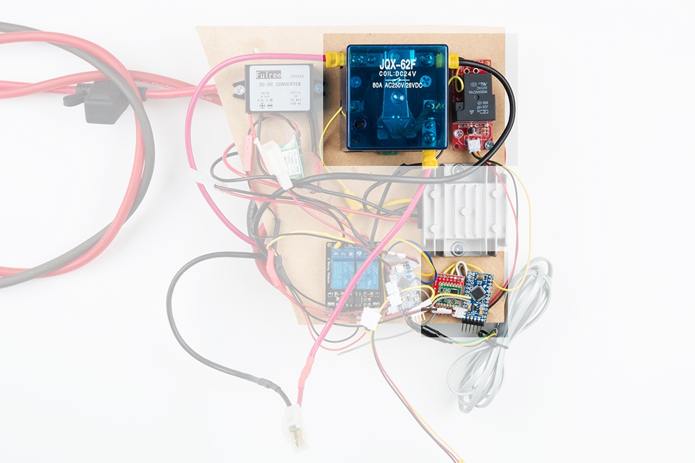
I’ve decided to run my PRS vehicle at 48V, which is the higher end of allowed system voltages. Luckily, there are some really nice DC to DC buck converters to get 48V down to 24V (to control the cut-off relay) and 5V (to power the 3.3V Pro Mini). See the parts list for links to the particular ones I used.
Under load and at top speed, the motor controller will be putting out 10's of amps at 48V. The VCU needs a substantial relay big enough to handle that load. Some of the lowest cost, highest current relays I could find were 24V relays. Because my 3.3V/8MHz Pro Mini can only turn on/off 3.3V, I decided to use a two relay setup.
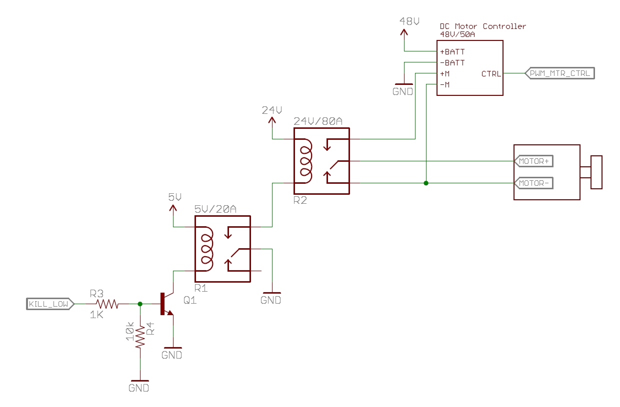
This is an example of a ‘bootstrapped’ relay system. Bootstrapping allows a small signal to control big loads. The 3.3V signal from the Pro Mini can’t control the large 24V relay directly, so I used the 3.3V signal to control a 5V relay to activate the 24V relay.
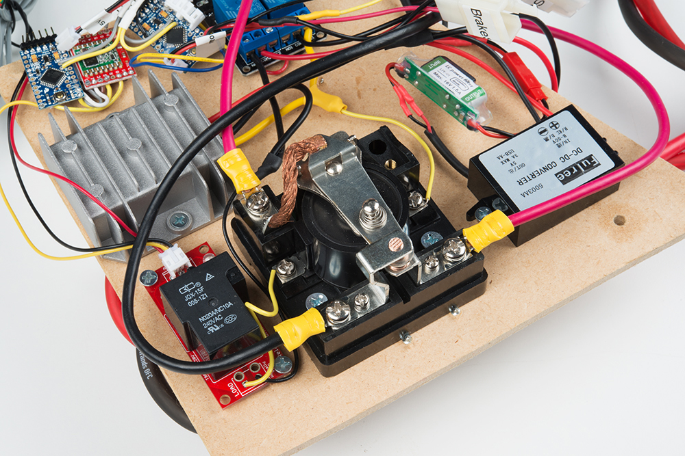
When we want to allow power to the motor, the Pro Mini activates the Beefcake Relay with a 3.3V signal (KILL_LOW goes from 0 to 3.3V). This signal grounds the Q1 transistor allowing current to flow across the coil in R1. Next, the reed on R1 moves from the normally closed position (where it is connected to nothing) to the normally open position. Current begins to flow freely from 24V through the R2 coil to ground. This flow causes the reed on R2 to move from the normally closed position to the upper position connecting the + lead of the motor to the +M on the motor controller. In real life, this whole process produces a most satisfying thunk. Note this does not power the motor; rather, it allows the motor controller to control the motor. If the motor controller is outputting 0% power, the motor will just sit happily still.
48V / 24V / 5V Subsystems
You may be wondering why I am running a 24V subsystem? For my A+PRS entry, I am controlling the steering with a 12V linear actuator that I am over-driving with 24V. The actuator is very strong but slow, and the extra voltage drives the actuator much faster. The 24V cut-off relay (R2) fit nicely into this design as well.
Motor Braking
When R2 is in the normally closed (unactivated) position, the + and - of the motor are shorted together. This is called motor braking. To see what this feels like, find a large DC motor, and try spinning the axle. It should be relatively easy. Now, short + and - of the motor together; the axle will be considerably harder to turn. By setting R2 up this way we have another layer of safety in that, if everything goes wrong and the Kill Switch goes haywire, the system should fail safe, turn off all the relays, short the motor and brake to a stop. It is not yet clear to me how aggressive this braking power is. If the braking is too abrupt (as in it ejects the human rider) it could be more dangerous than it is helpful, in which case I will disconnect the MOTOR- from the lower pin of R2 and let the motor freewheel in the event of a safety shutdown. That way the human passenger has the ability to control braking with the brake rather than something they cannot control.