Hookup Guide for the Qwiic Motor Driver
Hardware Overview
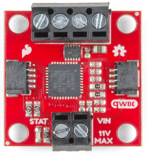
Let's look at some of the various features of the hardware.
Features:
- 1.5 A peak drive per channel, 1.2 A steady state
- Operates from 3 to 11 volts with 12v absolute max
- 3.3V default VCC and logic
- 127 levels of DC drive strength.
- Controllable by I2C or TTL UART signals
- Direction inversion on a per motor basis
- Global Drive enable
- Exposed small heat sink shape
- Several I2C addresses, default UART bauds available
Power
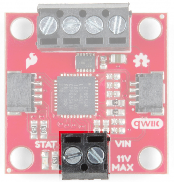
There are two separate power circuits on this board . Power for the motors is supplied through the VIN Connectors - you can provide anywhere from 3.3V to 11V to the "MAX 11V" and "GND" connections. Power for the PSOC and logic circuits is provided by the 3.3V inputs on the Qwiic connectors. Both are needed for proper functioning.
Qwiic Connectors
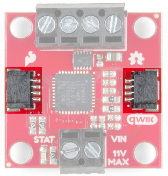
There are two Qwiic connectors on the board such that you can provide power or daisy-chain the boards should you choose to do so. If you're unfamiliar with our Qwiic system, head on over to our Qwiic page to see the advantages!
Motor Ports
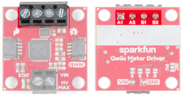
The screw pin terminals at the top of the board allow for two motor connections. They are labeled on the backside of the board.
| Function / Connection | ||||||
|---|---|---|---|---|---|---|
| Group | Name | Direction | Description | UART | I2C | |
| Motor Port | A1 | O | Winding of first addressable location | Motor A winding | ||
| A2 | O | Winding of first addressable location | Motor A winding | |||
| B1 | O | Winding of second addressable location | Motor B winding | |||
| B2 | O | Winding of second addressable location | Motor B winding | |||
Jumpers
Jumper Usage Table
There are 2 sets of jumpers to configure on this board. There are pull-up enables for I2C and 4 config bits that select operational mode.
| Name | Description | Usage |
|---|---|---|
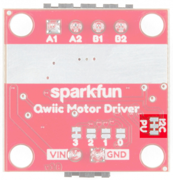
| I2C Jumpers | I2C pull-up enable | Opening these disables theI2C pull-up resistors used for I2C communication. If multiple I2C devices are being used, these pull-ups should be disabled on all but one device. If UART is being used, the pull-up resistors should be disabled. |
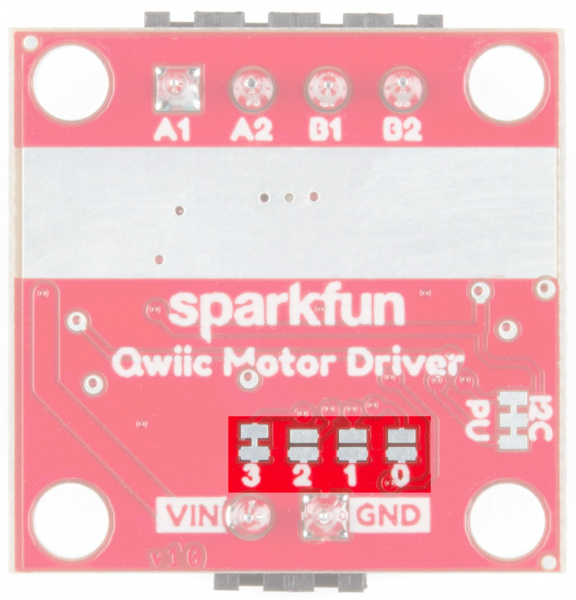
| Address Jumpers | Serial and function selection | The config bits are 4 bits that form a configuration nybble. A closed jumper is a '1' and an open jumper is a '0'. See config table for more information. |
I2C Pull-Up Jumpers
Address Bits
The configuration is set by encoding a number into the 4 config bits on the bottom of the board. Close a jumper to indicate a 1, or leave it open to indicate a 0.
Use this table to see what the user port, address, and expansion port will become in each configuration:
| Pattern | Mode | User Port | User Address | Expansion Port |
|---|---|---|---|---|
| 0000 | UART at 9600 | UART | N/A | Master |
| 0011 | I2C | I2C | 0x58 | Master |
| 0100 | I2C | I2C | 0x59 | Master |
| 0101 | I2C | I2C | 0x5A | Master |
| 0110 | I2C | I2C | 0x5B | Master |
| 0111 | I2C | I2C | 0x5C | Master |
| 1000 | I2C | I2C | 0x5D | Master |
| 1001 | I2C | I2C | 0x5E | Master |
| 1010 | I2C | I2C | 0x5F | Master |
| 1011 | I2C | I2C | 0x60 | Master |
| 1100 | I2C | I2C | 0x61 | Master |
| 1101 | UART at 57600 | UART | N/A | Master |
| 1110 | UART at 115200 | UART | N/A | Master |
| 1111 | N/A | Reserved | N/A | N/A |
Thermal Conduction Area
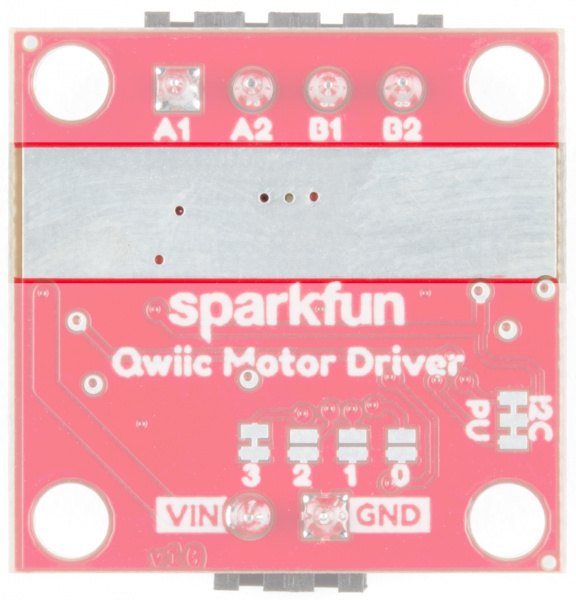
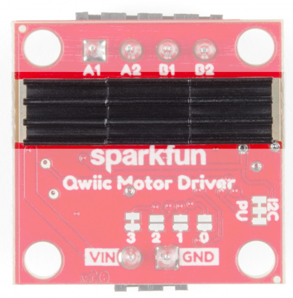
The Qwiic Motor Driver is designed to operate small robot drive motors without a heatsink; we were able to run up to about 1.1A continuous current without going above 100°C. If you find that you need a heatsink, you can use our Theragrip Thermal Tape to attach three Small Heat Sinks across the thermal conduction area on the back of the board.
If you need more information on how to determine whether or not you need a heat sink, kick on over to the Serial Controlled Motor Driver Hookup Guide and scroll down to Typical Application Motors and Heat Sinking.
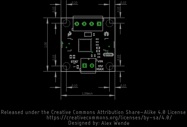
Board Dimensions
All measurements are in inches. The Qwiic Motor Driver PCB measures 1x1 inch, with slight overhangs for the power and motor screw terminals.
