Hookup Guide for the Qwiic Motor Driver
Experiment 1: Testing the Motors
Let's start by hooking up some motors and making sure they're running. Since the Qwiic Motor Driver uses the same PSOC as the Serial Controlled Motor Driver, the same examples will work with minor modifications.
Hardware Hookup
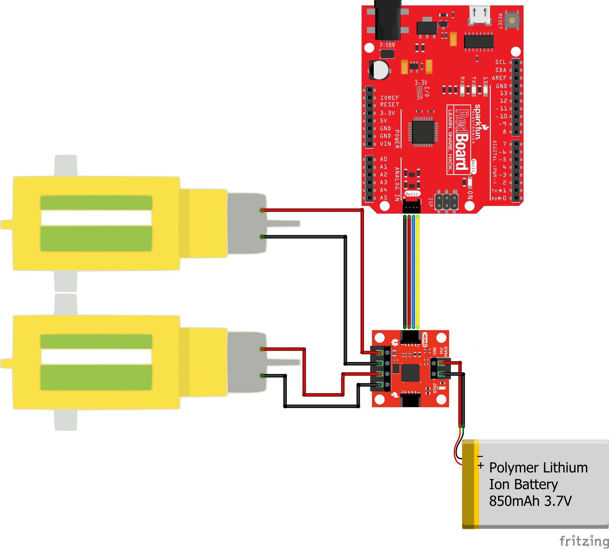
Testing the Motors
The following test is essentially the TwoMotorRobot.ino example from the SCMD library, but with a few minor changes to account for the defaults of the Qwiic Motor Driver.
Copy and paste the following code into your Arduino browser and upload.
language:c
//This example drives a robot in left and right arcs, driving in an overall wiggly course.
//  It demonstrates the variable control abilities. When used with a RedBot chassis,
//  each turn is about 90 degrees per drive.
//
//  Pin 8 can be grounded to disable motor movement, for debugging.

#include <Arduino.h>
#include <stdint.h>
#include "SCMD.h"
#include "SCMD_config.h" //Contains #defines for common SCMD register names and values
#include "Wire.h"

SCMD myMotorDriver; //This creates the main object of one motor driver and connected peripherals.

void setup()
{
  pinMode(8, INPUT_PULLUP); //Use to halt motor movement (ground)

  Serial.begin(9600);
  Serial.println("Starting sketch.");

  //***** Configure the Motor Driver's Settings *****//
  //  .commInter face is I2C_MODE
  myMotorDriver.settings.commInterface = I2C_MODE;

  //  set address if I2C configuration selected with the config jumpers
  myMotorDriver.settings.I2CAddress = 0x5D; //config pattern is "1000" (default) on board for address 0x5D

  //  set chip select if SPI selected with the config jumpers
  myMotorDriver.settings.chipSelectPin = 10;

  //*****initialize the driver get wait for idle*****//
  while ( myMotorDriver.begin() != 0xA9 ) //Wait until a valid ID word is returned
  {
    Serial.println( "ID mismatch, trying again" );
    delay(500);
  }
  Serial.println( "ID matches 0xA9" );

  //  Check to make sure the driver is done looking for peripherals before beginning
  Serial.print("Waiting for enumeration...");
  while ( myMotorDriver.ready() == false );
  Serial.println("Done.");
  Serial.println();

  //*****Set application settings and enable driver*****//

  //Uncomment code for motor 0 inversion
  //while( myMotorDriver.busy() );
  //myMotorDriver.inversionMode(0, 1); //invert motor 0

  //Uncomment code for motor 1 inversion
  while ( myMotorDriver.busy() ); //Waits until the SCMD is available.
  myMotorDriver.inversionMode(1, 1); //invert motor 1

  while ( myMotorDriver.busy() );
  myMotorDriver.enable(); //Enables the output driver hardware

}

#define LEFT_MOTOR 0
#define RIGHT_MOTOR 1
void loop()
{
  //pass setDrive() a motor number, direction as 0(call 0 forward) or 1, and level from 0 to 255
  myMotorDriver.setDrive( LEFT_MOTOR, 0, 0); //Stop motor
  myMotorDriver.setDrive( RIGHT_MOTOR, 0, 0); //Stop motor
  while (digitalRead(8) == 0); //Hold if jumper is placed between pin 8 and ground

  //***** Operate the Motor Driver *****//
  //  This walks through all 34 motor positions driving them forward and back.
  //  It uses .setDrive( motorNum, direction, level ) to drive the motors.

  //Smoothly move one motor up to speed and back (drive level 0 to 255)
  for (int i = 0; i < 256; i++)
  {
    myMotorDriver.setDrive( LEFT_MOTOR, 0, i);
    myMotorDriver.setDrive( RIGHT_MOTOR, 0, 20 + (i / 2));
    delay(5);
  }
  for (int i = 255; i >= 0; i--)
  {
    myMotorDriver.setDrive( LEFT_MOTOR, 0, i);
    myMotorDriver.setDrive( RIGHT_MOTOR, 0, 20 + (i / 2));
    delay(5);
  }
  //Smoothly move the other motor up to speed and back
  for (int i = 0; i < 256; i++)
  {
    myMotorDriver.setDrive( LEFT_MOTOR, 0, 20 + (i / 2));
    myMotorDriver.setDrive( RIGHT_MOTOR, 0, i);
    delay(5);
  }
  for (int i = 255; i >= 0; i--)
  {
    myMotorDriver.setDrive( LEFT_MOTOR, 0, 20 + (i / 2));
    myMotorDriver.setDrive( RIGHT_MOTOR, 0, i);
    delay(5);
  }
}
What You Should See
The code goes through and establishes communication with the motor driver and then runs each motor in arcs, resulting in a "wiggly pattern".
Things to note:
Serial.beginis periodically run until the returned ID word is valid.- Setup waits for
isReady()to become true before going on to the drive section - One motor is inverted by command at setup. Do it here so you don't have to mess with it later.
enable()is called to connect the drivers to the PWM generators.- LEFT_MOTOR and RIGHT_MOTOR are defined to ease use of the
setDrive( ... )function.
See the Arduino Library Reference section of the Serial Controlled Motor Driver Hookup Guide for more information on the functions defined in the Arduino library.